Intelligent lock with heating structure

A heating structure and smart lock technology, applied in the field of smart locks, can solve the problems of affecting the service life of smart locks, reducing the practicability of smart locks, reducing user experience effects, etc., to achieve convenient inspection and maintenance, convenient disassembly, and improved comfort Effect

Active Publication Date: 2021-07-13
DESSMANN CHINA MACHINERY & ELECTRONICS
View PDF8 Cites 0 Cited by
  • Summary
  • Abstract
  • Description
  • Claims
  • Application Information

AI Technical Summary

Problems solved by technology

[0004] In an "intelligent lock", it can heat the user's fingers through the heating mechanism, thereby improving the accuracy of fingerprint recognition, making the recognition accuracy of the smart lock higher, and using the heat from the smart lock itself to perform smart lock The recognition degree is improved, but the surface temperature of the smart lock is low when used in winter. Direct contact with the smart lock will affect the experience and reduce the practicability of the smart lock. When the smart lock is not working, the heat generated by itself is not enough to protect the The heating of the smart lock, especially in winter, will cause the temperature of the smart lock to be too low and not have the antifreeze function. While reducing the user experience effect, the lower temperature will also reduce the temperature of the smart lock. When the smart lock is heated, the heating source is located at The interior of the smart lock will cause damage to the parts and affect the service life of the smart lock
There is still no smart lock with a heating structure that is reasonable and reliable in structure, easy to install and antifreeze.

Method used


Image

  • Intelligent lock with heating structure
  • Intelligent lock with heating structure
  • Intelligent lock with heating structure

Examples


Embodiment Construction

[0032] In order to enable those skilled in the art to better understand the solution of the present application, the technical solution in the embodiment of the application will be clearly and completely described below in conjunction with the accompanying drawings in the embodiment of the application. Obviously, the described embodiment is only It is an embodiment of a part of the application, but not all of the embodiments. Based on the embodiments in this application, all other embodiments obtained by persons of ordinary skill in the art without creative efforts shall fall within the scope of protection of this application.

[0033] It should be noted that the terms "first" and "second" in the description and claims of the present application and the above drawings are used to distinguish similar objects, but not necessarily used to describe a specific sequence or sequence. It should be understood that the data so used may be interchanged under appropriate circumstances for...


PUM


Abstract

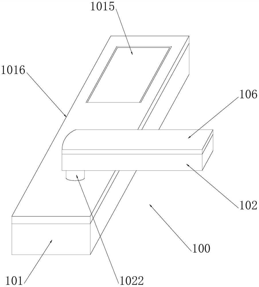
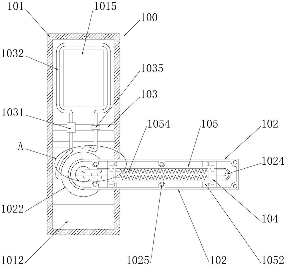
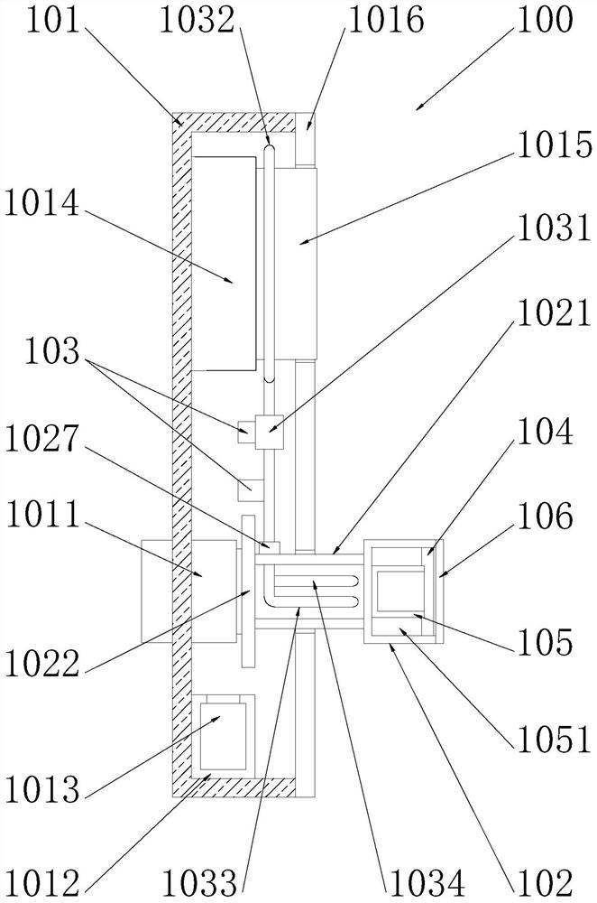
The invention discloses an intelligent lock with a heating structure. The intelligent lock comprises a lock body, a lock shell, a storage box, a drying agent, a fingerprint identifier, a fingerprint touch screen, a lock cover, a handle, a connecting shaft, a fixed plate, a fixed shell, a heat exchange pipe, a threaded hole, a bolt, a connector, a supporting plate, a micro water pump, a heating pipe, a water inlet pipe, a water outlet pipe, a fixed buckle, a partition plate, a protective shell, a fixed block, an elastic piece, a clamping block, an electric heating wire, a cover body, a pressing plate and a notch. The intelligent lock has the beneficial effects that a heating source can be arranged on the handle to heat the handle, the anti-freezing problem in winter is achieved, the surface of the intelligent lock can be heated, the heating source is arranged on the handle, the situation that the heating source directly heats the interior of the intelligent lock can be avoided, and the problem that the heating source damages the intelligent lock is solved; and heat exchange is achieved through a closed pipeline, it can be guaranteed that the surface heating temperature of the intelligent lock is appropriate, and meanwhile the fixed shell and the cover body can prevent the heating source at the handle from making direct contact with a user.

Description

technical field [0001] The invention relates to an intelligent lock with a heating structure, in particular to an intelligent lock with a heating structure, and belongs to the technical field of application of intelligent locks. Background technique [0002] Smart locks refer to locks that are more intelligent in terms of user identification, security, and management, which are different from traditional mechanical locks. Smart locks are the executive components for locking doors in the access control system. Electronic locks cannot be called smart locks. The sign of smart locks is whether they can be linked and operated by mobile phones. The current smart lock is different from the previous method of first opening and then scanning. The scanning method is very simple. Put your finger on the scanning place Scan from top to bottom on the top, no need to press your finger on the scanning place, the scanning method reduces fingerprint residues, greatly reduces the possibility o...

Claims


Application Information

Patent Timeline
Patent Type & Authority Applications(China)
IPC IPC(8): E05B1/00E05B3/00E05B15/00E05B17/00E05B49/00F26B5/16
CPCE05B15/00E05B1/003E05B3/00E05B17/0016E05B49/00E05B17/0004F26B5/16
Inventor 黄兴主
Owner DESSMANN CHINA MACHINERY & ELECTRONICS
Why Eureka
Try Eureka