
Heat exchange assembly capable of achieving switching of working conditions and heat exchanger

A technology of heat exchange components and working conditions, applied in indirect heat exchangers, tubular elements, heat exchange equipment, etc., can solve the problem of uncontrolled heat exchange efficiency adjustment, inability to adjust the opening degree heat exchange efficiency, and difficult to meet heat exchange Fast switching of the device to achieve the effect of prolonging the service life and overcoming the easy blockage

Active Publication Date: 2021-07-13
QINGDAO TECHNOLOGICAL UNIVERSITY
View PDF7 Cites 5 Cited by
  • Summary
  • Abstract
  • Description
  • Claims
  • Application Information

AI Technical Summary

Problems solved by technology

[0003] The inventors found that the pressure drop of the fluid in the capillary is linear, and as the number of capillary arranged in parallel in the heat exchanger increases, some capillary will be cut off or backflow due to the pressure drop, which will affect the overall heat transfer efficiency of the heat exchanger
At present, for the adjustment of the heat exchange efficiency of the heat exchanger, the flow of the main pipe is mostly adjusted through the opening of the valve, and as the opening of the valve decreases, the flow inside the capillary network will also change, resulting in inaccurate adjustment of the heat exchange efficiency. Controlled, the adjustment opening cannot correspond to the actual heat exchange efficiency, especially for the proportional adjustment of heat exchange efficiency, it is difficult to meet the needs of the heat exchanger for rapid switching of working conditions; in addition, for the heat exchange requirements of various working conditions that vary greatly Scenarios, especially for the capillary heat exchange system buried in the lining of the subway tunnel, although the change of the working condition can be realized by adjusting the opening of the valve, the precise adjustment after changing the working condition is still not possible, and the adjustment process can only rely on the dry water supply. The valve adjustment on the road is difficult to meet the adjustment requirements of heat exchange efficiency in multiple working conditions

Method used


Image

  • Heat exchange assembly capable of achieving switching of working conditions and heat exchanger
  • Heat exchange assembly capable of achieving switching of working conditions and heat exchanger
  • Heat exchange assembly capable of achieving switching of working conditions and heat exchanger

Examples


Embodiment 1

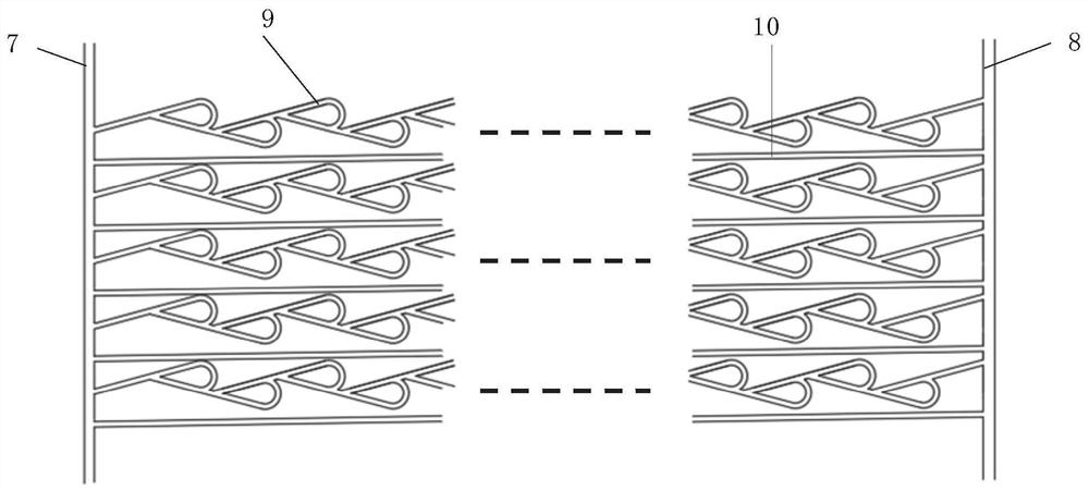
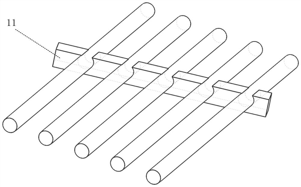
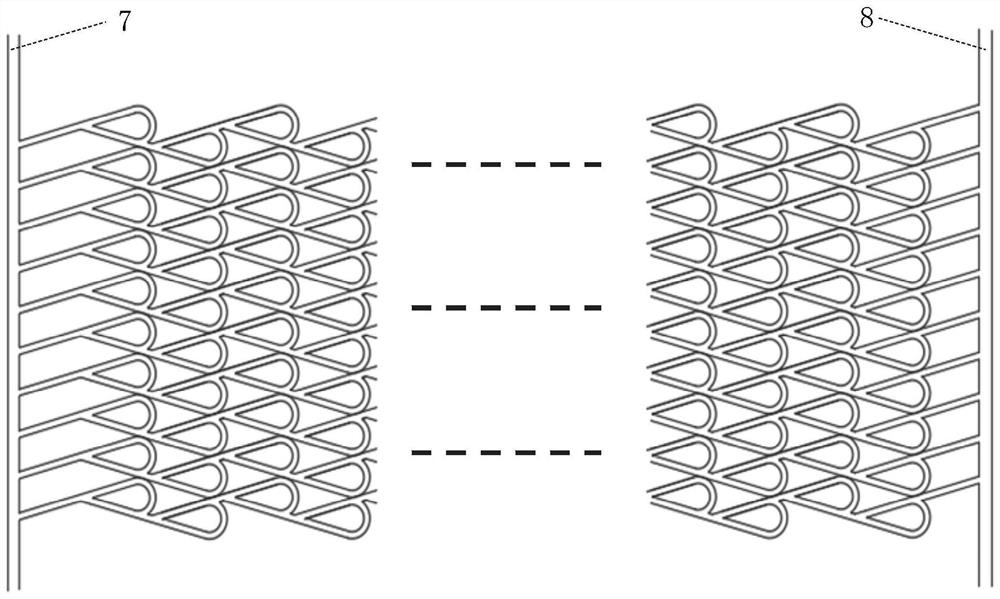
[0031] In a typical implementation of the present disclosure, such as Figure 1-Figure 5 As shown, a heat exchange component with switchable working conditions is proposed.

[0032] Including trunk tube and capillary group, the two trunk tubes form a pair, the two trunk tubes are connected through the capillary group, one trunk tube is used as the liquid inlet tube 7 to input the medium into the capillary group, and the other dry tube The road pipe is used as the drain pipe 8 to recover the medium output by the capillary group, and the capillary group performs heat exchange with the external environment through the internal medium.

[0033] The flow direction of the medium in the two main pipes can be changed. The two main pipes are respectively connected to the two ports of the reversing valve, and the other two ports of the reversing valve are connected to the external water supply pipe and the return pipe; The position can make the water supply pipe communicate with differ...

Embodiment 2

[0061] In another typical implementation of the present disclosure, such as Figure 1-Figure 5 As shown, a heat exchanger is proposed, which utilizes the heat exchange assembly with switchable working conditions as described in Embodiment 1.

[0062] The heat exchange components in the heat exchanger adopt the heat exchange components that can switch working conditions as in Example 1.

[0063] It can be understood that in the same heat exchanger, multiple sets of heat exchange components that can switch working conditions can be arranged in parallel, and all heat exchange components can be controlled by a four-way reversing valve to realize the overall heat exchange of the heat exchanger. Efficiency adjustments;

[0064] It is also possible to configure a four-way reversing valve for each group of heat exchange components. By controlling the reversing valves one by one, more precise control of the overall heat exchanger efficiency can be achieved.


PUM


Abstract

The invention provides a heat exchange assembly capable of achieving switching of working conditions and a heat exchanger, and relates to the field of capillary tube heat exchange. The heat exchange assembly capable of achieving switching of the working conditions comprises main line pipes and a capillary tube group; a reversing valve is connected in, the pair of main line pipes are communicated through the capillary tube group, and the reversing valve is used for switching the flow direction of media in the capillary tube group; and the capillary tube group comprises a first heat exchange branch tube and a second heat exchange branch tube which are arranged in parallel, wherein the first heat exchange branch tube is a two-way conduction capillary tube, and the second heat exchange branch tube is a one-way conduction capillary tube connected with a Tesla valve in series. The two-way circulation capillary tube and the one-way circulation capillary tube are adopted, through the difference between the working states of the capillary tubes during forward flow and reverse flow, the flow directions in the capillary tubes are switched through the reversing valve, and rapid switching of the working conditions can be achieved without adjusting the opening degree of the valve.

Description

technical field [0001] The disclosure relates to the field of capillary heat exchange, in particular to a heat exchange assembly and a heat exchanger with switchable working conditions. Background technique [0002] As a kind of heat exchanger, capillary heat exchanger has high heat exchange efficiency and its application field is gradually expanding. However, due to the small diameter of the tube, the flow rate of the medium in the tube is relatively slow, and the medium in the tube can fully exchange heat with the environment outside the tube, which improves its heat exchange efficiency. [0003] The inventors found that the pressure drop of the fluid in the capillary is linear, and as the number of capillary arranged in parallel in the heat exchanger increases, some capillary will be cut off or backflow due to the pressure drop, which will affect the overall heat exchange efficiency of the heat exchanger. At present, for the adjustment of the heat exchange efficiency of ...

Claims


Application Information

Patent Timeline
IPC IPC(8): F28D15/00F28F27/02F28F1/00
CPCF28D15/00F28F27/02F28F1/00
Inventor 季永明吴汶泽胡松涛刘国丹佟振童力
Owner QINGDAO TECHNOLOGICAL UNIVERSITY
Learn More