Rail transit converter air cooling system test device and method

An air-cooling system and rail transit technology, which is applied in the cooling field of rail transit vehicles, can solve the problems of difficulty in arranging measuring points, small internal space, and large test equipment, and achieve convenient operation of data collection on the test site and reduce equipment Volume, the effect of increasing the test space

Pending Publication Date: 2021-07-13
CHINA ACADEMY OF RAILWAY SCI CORP LTD +3
View PDF0 Cites 0 Cited by
  • Summary
  • Abstract
  • Description
  • Claims
  • Application Information

AI Technical Summary

Problems solved by technology

[0003] First, the entire test device is huge and the test method is complicated; at present, the power unit converter tends to be miniaturized gradually, with a high degree of integration and a small internal space, so it is difficult to arrange corresponding measuring points and carry out relevant test research; and now Some converter air-cooling system test data only have the air flow rate at the inlet of the cooling device, so only parameters such as air flow can be calculated
[0004] Second, the air-cooling system and the water-cooling system in the entire power unit converter will work at the same time. When the complete power unit converter is used for the test, the measured test data is the data under the joint cooling of the air-cooling system and the water-cooling system ; and in addition to the cooled devices that need air cooling, there will be other electrical devices that do not need air cooling in the dirty room, and the wind will flow through these electrical devices to some extent during the test; this makes the final measured data It is not the data under the simple action of the air cooling system, and it is impossible to accurately measure the quantitative data under the air cooling effect of the air cooling system on the cooled device alone
Therefore, the existing converter air-cooled system tests are not able to study the properties of the air-cooled system in depth

Method used


Image

  • Rail transit converter air cooling system test device and method
  • Rail transit converter air cooling system test device and method
  • Rail transit converter air cooling system test device and method

Examples


Embodiment Construction

[0048] In order to have a clearer understanding of the technical features, purposes and effects of the present invention, the specific implementation manners of the present invention will now be described with reference to the accompanying drawings.

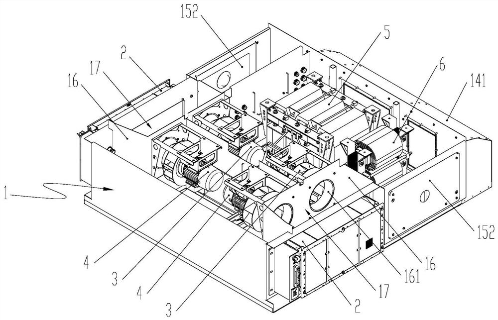
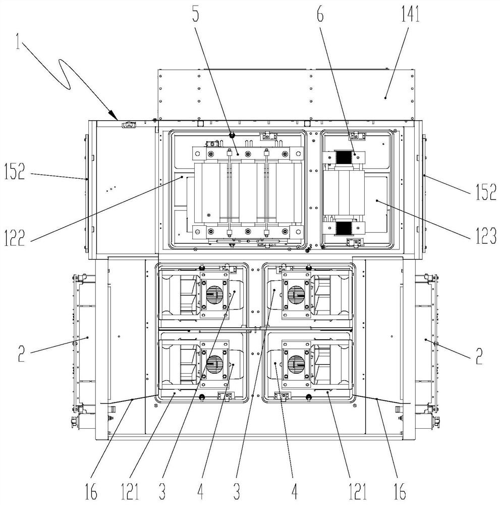
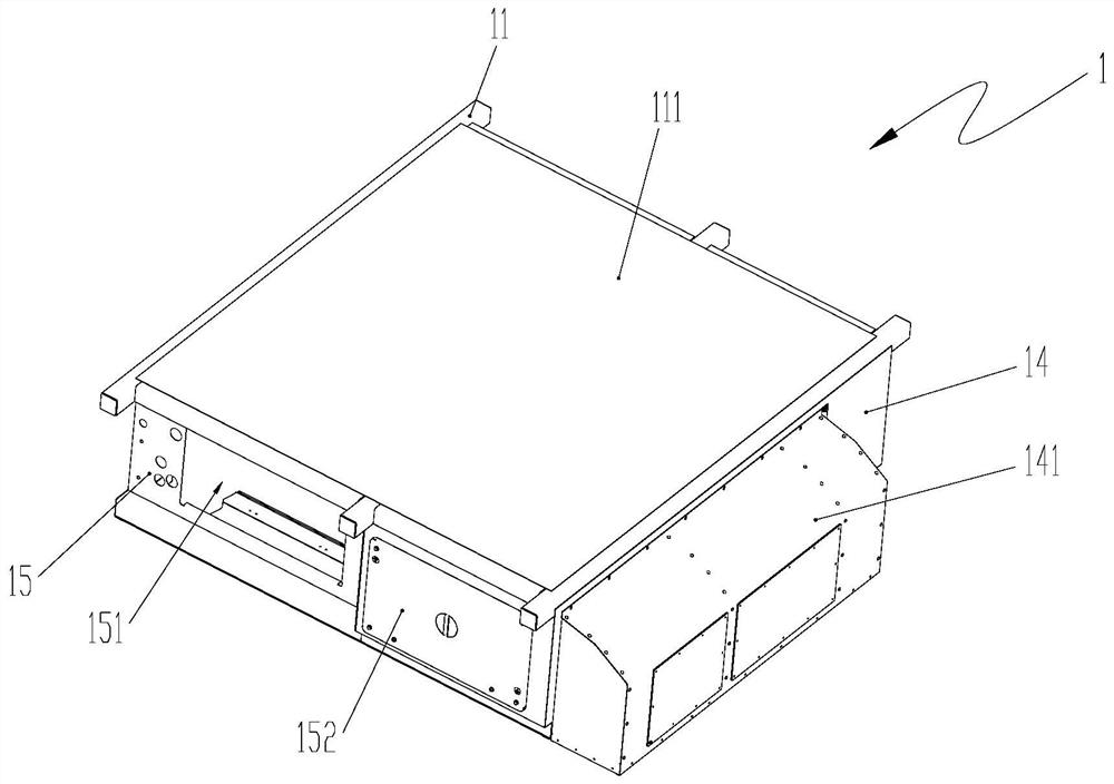
[0049] Such as Figure 1 to Figure 5 As shown, the present embodiment provides a test device for the air-cooling system of a rail transit converter, which includes a test box 1 in the shape of a rectangular body, and an overall inlet is arranged symmetrically on both sides of the test box 1 and near its first end. The tuyere 151 is provided with a windshield 16 with a through hole 161 at the position corresponding to each general air inlet 151 in the test chamber 1, and the windshield 16 is enclosed with the test chamber 1 to form a connection with the corresponding total air inlet 151. The air guide cavity 17 is equipped with radiators 2 on the outside of both sides of the test box 1 at positions opposite to the total air inlets...


PUM


Abstract

The invention relates to a rail transit converter air cooling system test device and method. The rail transit converter air cooling system test device comprises a test box, main air inlets are symmetrically formed in the positions, close to the first end, of the two side faces of the test box, wind shields with through holes are arranged in the test box, and radiators are fixedly arranged at the positions, right opposite to the main air inlets, of the exteriors of the two sides of the test box. A first fan is arranged in a fan mounting chamber formed between the two wind shields. An auxiliary transformer and a resonance reactor are arranged in the test box and close to the second end of the test box, and a first air outlet is formed in the bottom surface of the test box and close to the second end of the test box. The device is small in size, convenient to install and easy to operate, can be used for testing data under the independent action of an air cooling system, and is more convenient for deeply researching the attributes of the air cooling system.

Description

technical field [0001] The invention relates to the technical field of cooling of rail transit vehicles, in particular to a test device and a test method for an air cooling system of a rail transit converter. Background technique [0002] The power unit converter is an important high-mass electrical component on a high-speed EMU, and all functions of the traction converter, auxiliary converter and cooling unit are integrated in its box. Among them, the traction converter mainly includes traction control unit, power module, contactor, resonant capacitor, etc., the auxiliary converter mainly includes auxiliary transformer, resonant reactor, etc., and the cooling unit includes fan, radiator, water pump, cooling water pipe, etc. The air-cooling system part in the cooling unit can be used to air-cool the radiator, auxiliary transformer and resonance reactor in the auxiliary converter, and the power module in the traction converter can be water-cooled by using the water-cooling pa...

Claims


Application Information

Patent Timeline
Patent Type & Authority Applications(China)
IPC IPC(8): G01N25/20G01M99/00G01D21/02
CPCG01N25/20G01M99/002G01D21/02
Inventor 刘秀川刘直康晶辉李阳陶元之刘伟志董鑫媛宋术全张建军刘德剑
Owner CHINA ACADEMY OF RAILWAY SCI CORP LTD
Why Eureka
Try Eureka