High-voltage multifunctional power supply
A multi-functional, high-voltage technology, applied in electrical components, output power conversion devices, AC power input conversion to AC power output, etc., can solve problems such as poor practicability, low voltage level of equipment, poor safety, etc., and achieve voltage stability , Increase the voltage level and reduce the impact effect
- Summary
- Abstract
- Description
- Claims
- Application Information
AI Technical Summary
Problems solved by technology
Method used
Image

Examples
Embodiment 1
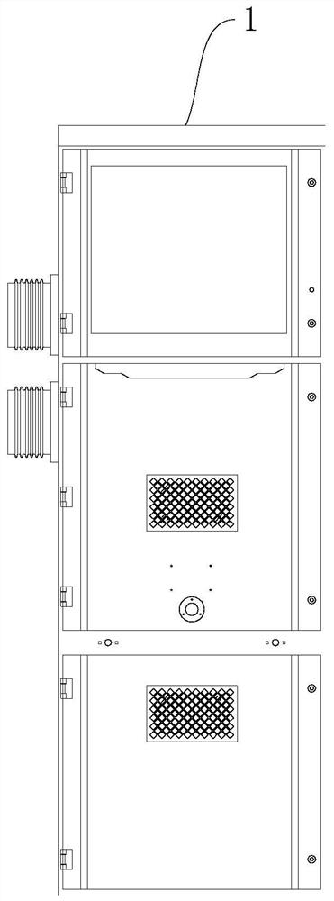
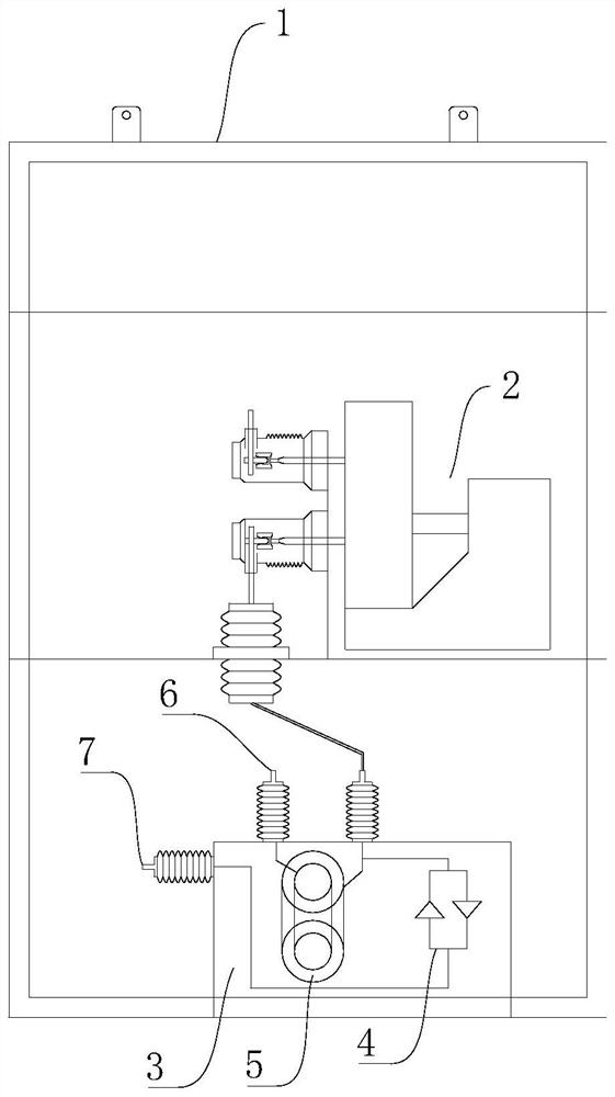
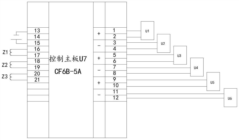
[0048] Please refer to figure 1 , figure 2 , Figure 5 with Figure 6 , figure 1 A structural diagram of the overall structure of the first embodiment of the present invention; figure 2 A partial view of the internal portion of the power cabinet main body 1 in Example 1 to Example 5 of the present invention; Figure 5 A connection schematic of a primary line in the first embodiment of the present invention; Figure 6 A connection block diagram of the main control mechanism in Example 1- Embodiment 5 of the present invention.
[0049] This embodiment provides a high voltage multifunctional power source including the power cabinet main body 1, and the power cabinet main body 1 is provided with a primary line, and the main control mechanism of accessing a line; the main control mechanism is used to adjust the input voltage Pressure, transfer, speed control, and post-voltage output;
[0050] The primary line includes circuit breaker SB12, a charged display G1, and a transformer TC15;
[0...
Embodiment 2
[0057] Please refer to figure 1 , figure 2 with Figure 6 , figure 1 A structural diagram of the overall structure of the first embodiment of the present invention; figure 2 A partial view of the internal portion of the power cabinet main body 1 in Example 1 to Example 5 of the present invention; Figure 6 A connection block diagram of the main control mechanism in Example 1- Embodiment 5 of the present invention.
[0058] In the present embodiment, the output terminal of the circuit breaker SB 12 is connected to the input of the main control mechanism; and the main control mechanism and the transformer TC 15 are located in the mount 3 filled with insulating oil. The oil immersion sealing structure is used, the size is small, and the insulation is high, so that the stability is strong.
Embodiment 3
[0060] Please refer to figure 1 , figure 2 , image 3 , Figure 4 with Figure 6 , figure 1 A structural diagram of the overall structure of the first embodiment of the present invention; figure 2 A partial view of the internal portion of the power cabinet main body 1 in Example 1 to Example 5 of the present invention; image 3 A connection schematic view of the main control circuit in Example 3- in Examples of the Examples of the Example 3- in Examples Figure 4 The connection schematic of the amplification circuit and the protection circuit is shown in Embodiment 3 to Example 5 of the present invention; Figure 6 A connection block diagram of the main control mechanism in Example 1- Embodiment 5 of the present invention.
[0061] In the present embodiment, the main control mechanism includes a master circuit, an amplified circuit of an access primary circuit, and a protection circuit for accessing an amplified circuit.
[0062] In the present embodiment, the main control circuit inclu...
PUM
 Abstract
Description
Claims
Application Information
 - R&D
- Intellectual Property
- Life Sciences
- Materials
- Tech Scout
- Unparalleled Data Quality
- Higher Quality Content
- 60% Fewer Hallucinations
Browse by: Latest US Patents, China's latest patents, Technical Efficacy Thesaurus, Application Domain, Technology Topic, Popular Technical Reports.
© 2025 PatSnap. All rights reserved.Legal|Privacy policy|Modern Slavery Act Transparency Statement|Sitemap|About US| Contact US: help@patsnap.com