
Flow congestion isolation method, device and system

A technology of traffic congestion and service flow, applied in the field of communication, it can solve the problems of transmission rate reduction and impact, and achieve the effect of avoiding transmission

Active Publication Date: 2021-07-13
紫光华山科技有限公司
View PDF6 Cites 0 Cited by
  • Summary
  • Abstract
  • Description
  • Claims
  • Application Information

AI Technical Summary

Problems solved by technology

However, when a device on a ROCE network forwards all service flows, it stores the service packets of all service flows in the same packet forwarding queue for forwarding. , it will affect the non-congested normal business flows existing in the message forwarding queue, resulting in the transmission rate of these non-congested normal business flows in the ROCE network is also reduced

Method used


Image

  • Flow congestion isolation method, device and system
  • Flow congestion isolation method, device and system
  • Flow congestion isolation method, device and system

Examples


Embodiment 1

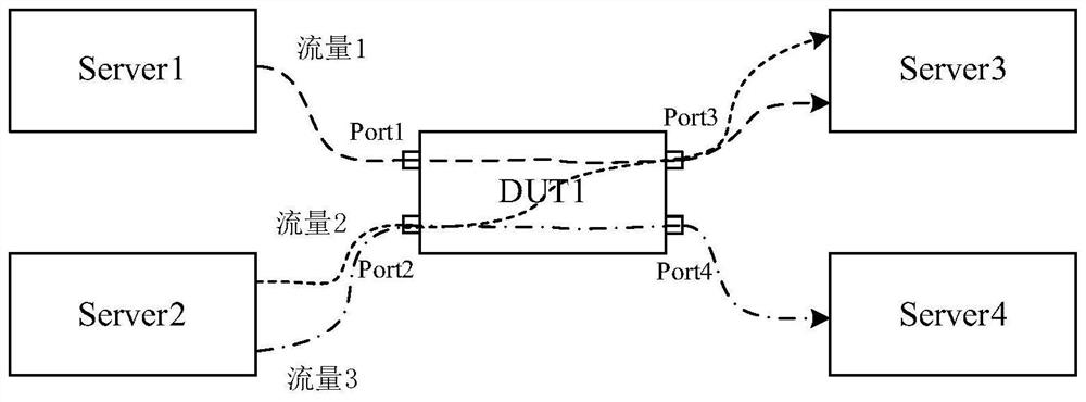
[0087] This embodiment 1 is applied to such as Figure 4 In the shown ROCE networking architecture, Figure 4 The DUT device is a switch, the Server is a server, and the Controller is a controller. There is a connection between the switch and the controller, and there is a connection between the switch and the server. All devices here are configured with ECN function and PFC function, and each switch is configured with ERSPAN mirror function and two different queues, one of which is initially used to store service packets of all service flows without congestion In the initial situation, when the switch receives the service packets of service flow 1, service flow 2, and service flow 3, it stores them in the packet forwarding queue for forwarding. The other queue is used for congested service flows. When the congestion occurs, the congestion reserved queue stores the service packets of the congested service flow. At the beginning, the congestion reserved queue does not need to ...

Embodiment 2

[0102] This embodiment 2 is applied to such as Figure 6 In the shown ROCE networking architecture, Figure 6 In the shown networking architecture, the controller is connected to the server, and other configurations on the device are the same as those in Embodiment 1.

[0103] The following pass as Figure 7 The shown flow chart describes the present embodiment 2:

[0104] Step 701, when the switch detects that the buffer occupancy of any ingress port receiving a service flow exceeds the first waterline value used to indicate congestion, determine that the service flow received by the ingress port is congestion at the egress port For the service flow, for the service packets of the congested service flow currently stored in the message forwarding queue of the switch, modify the uncongested flag in the service packet of the congested traffic flow to a congested flag and forward it.

[0105] Step 702, when the second server receives a service message carrying a congestion fla...


PUM


Abstract

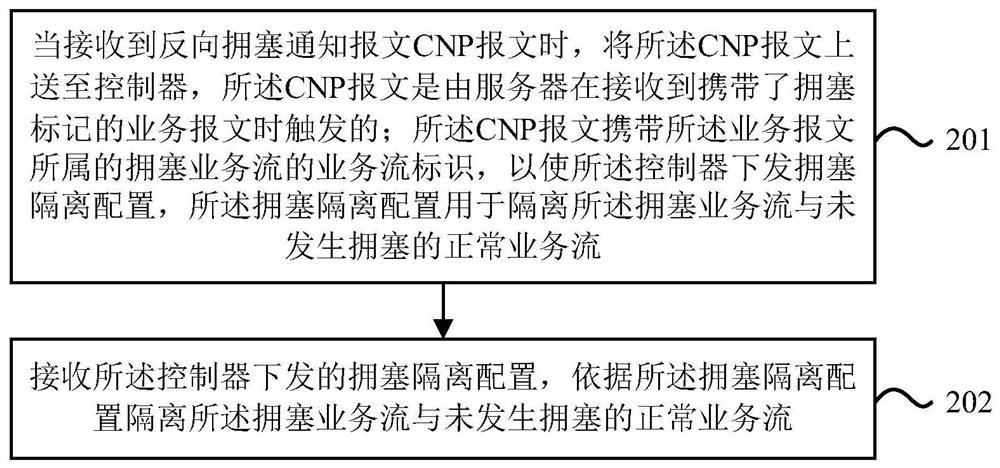
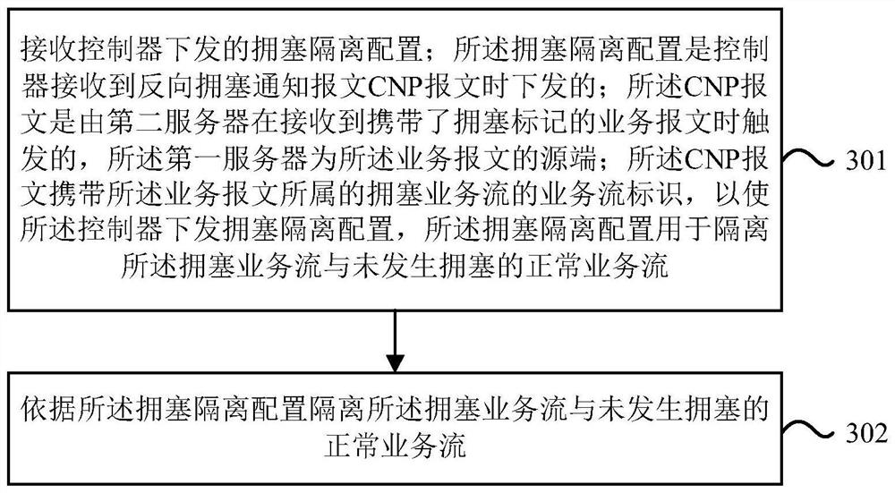
The embodiment of the invention discloses a traffic congestion isolation method, device and system. In the application, after a switch or a server (referring to a source end of a congestion service flow) receives a congestion isolation configuration issued by a controller, the congestion service flow can be isolated from a normal service flow which is not congested according to the congestion isolation configuration; wherein the congestion isolation configuration is issued when the controller receives a reverse congestion notification message CNP message, and the reverse congestion notification message CNP message is triggered when another server receives a service message carrying a congestion mark. According to the scheme provided by the invention, the congestion service flow is isolated from the normal service flow which is not congested, so that the transmission of the normal service flow which is not congested can be prevented from being influenced when the congestion occurring in the congestion service flow is further eliminated.

Description

technical field [0001] The present application relates to the communication field, and in particular to a traffic congestion isolation method, device and system. Background technique [0002] In order to solve the problem of server-side data processing delay during service flow transmission in the network, ROCE (RDMA over Converged Ethernet, Ethernet-based RDMA technology) technology has been used in some data center networks. Using RDMA (Remote Direct Memory Access, remote direct data access) technology can have a high forwarding bandwidth in the case of no damage or packet loss during the transmission of business packets of business flows, but the RDMA technology has a high forwarding bandwidth for business packets of business flows. The problem of delay or packet loss is relatively sensitive, especially when the service flow transmitted in the ROCE network is congested and causes packet loss, it will cause large-scale retransmission of service packets of the service flow,...

Claims


Application Information

Patent Timeline
Patent Type & Authority Applications(China)
IPC IPC(8): H04L12/801H04L12/833H04L47/31
CPCH04L47/12H04L47/31
Inventor 张建超
Owner 紫光华山科技有限公司
Learn More