A surface-enhanced inner step shaft inner hole precision forming process
What is AI technical title?
AI technical title is built by Patsnap AI team. It summarizes the technical point description of the patent document.
A surface strengthening and precision forming technology, applied in the field of machining, can solve the problems of damaged mandrel forming, long cycle, low efficiency, poor coaxiality, etc. Effect
Active Publication Date: 2022-03-18
XI AN JIAOTONG UNIV +1
View PDF0 Cites 0 Cited by
Summary
Abstract
Description
Claims
Application Information
AI Technical Summary
This helps you quickly interpret patents by identifying the three key elements:
Problems solved by technology
Method used
Benefits of technology
Problems solved by technology
[0005] The traditional deep hole drilling is used for manufacturing, the cycle is long, the efficiency is low, and the scrap rate is high, and the large holes are processed from both sides separately, which is prone to problems such as poor coaxiality and straightness.
Using the usual rotary forging process that uses pipes as blanks, for shafts with a large change in the inner hole step or a shaft with a requirement for the outer circle size, the rotary forging may damage the mandrel or fail to form.
Method used
Image
Click on the blue label to locate the original text in one second.
Reading with bidirectional positioning of images and text.
Examples
Embodiment 1
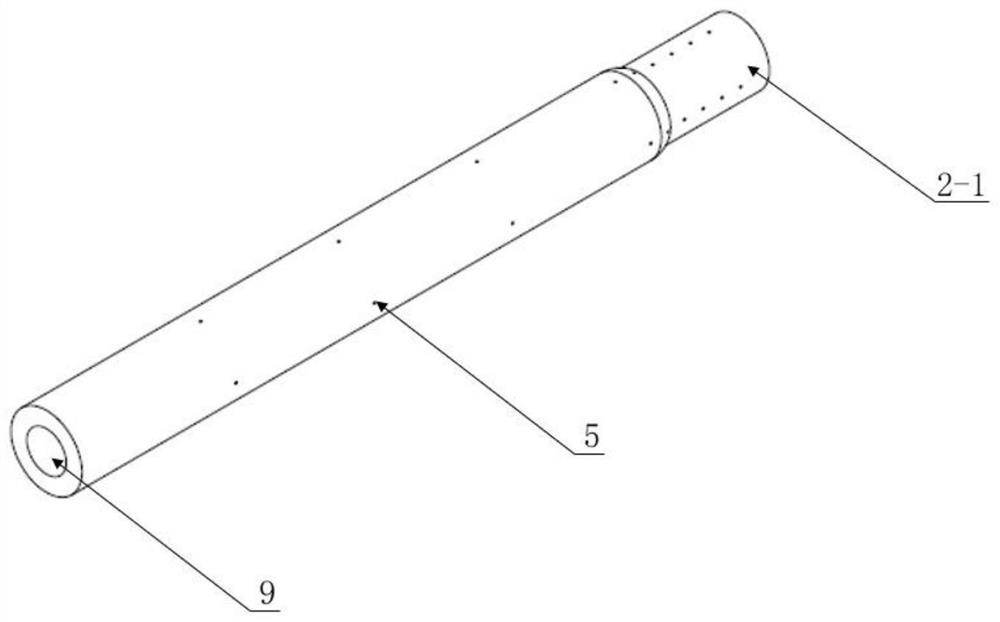
[0044] Embodiment 1, using the integral mandrel 2-1, a surface-strengthened internal step shaft inner hole precision forming process, including the following steps:
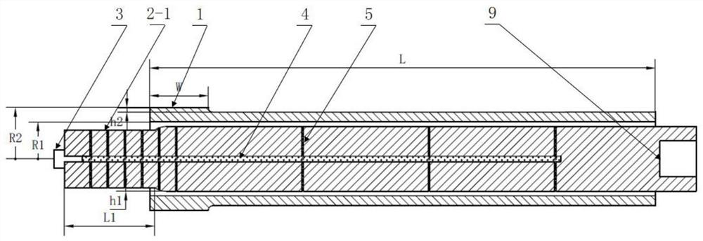
[0045] 1) Design blank: refer to image 3 , the design length of blank 1 is L, the design inner and outer diameters are R1 and R2 respectively, the length of the raised part of the blank is W, and the height of the raised part is h2; Step length L1; billet 1 design reference ratio W:L1:(h2-h1)=(6~7):(9~10):1, the more refined billet 1 size design needs to be based on finite element simulation and experimental experience results Pick;
[0046] 2) Remove the lubricant plug 3 of the integral mandrel 2-1, pump lubricant into the lubricant main channel 4 of the integral mandrel 2-1, so that the pumped lubricant fills the lubricant main channel 4, lubricant In the inner area formed by the shunt channel 5, after the pumping is completed, the lubricant plug 3 is installed to prevent the lubricant from leaking;
[0047...
Embodiment 2
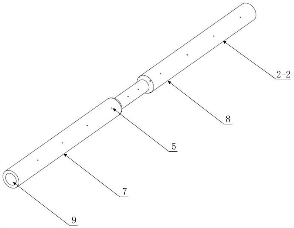
[0051] Embodiment 2, using the split mandrel 2-2, a surface-strengthened internal step shaft inner hole precision forming process, including the following steps:
[0052] 1) Design blank: refer to Image 6 , the design length of blank 1 is L, the design inner and outer diameters are R1 and R2 respectively, the length of the raised part of the blank is W, and the height of the raised part is h2; -2 step length L1; billet 1 design reference ratio W:L1:(h2-h1)=(6~7):(9~10):1, the more refined billet 1 size design needs to be based on finite element simulation and experimental experience results to fetch;
[0053] 2) Remove the lubricant plug 3 of the split mandrel 2-2, pump lubricant into the main lubricant channel 4 of the split mandrel 2-2, and make the pumped lubricant fill the main lubricant channel 4, The internal area formed by the lubricant flow channel 5, after the pumping is completed, the lubricant plug 3 is installed to prevent the lubricant from leaking;
[0054] 3...
PUM
Abstract
A surface-strengthened inner step shaft precision forming process, first design the blank, and then pump lubricant into the inner area formed by the lubricant-filled main flow channel and the lubricant branch channel of the mandrel; then assemble the mandrel and the blank, Install the rotary forging machine through the installation hole at the back of the mandrel, the mandrel and the blank are subjected to the high-frequency forging of the forging die, and the rotary forging forms a large inner hole; then adjust the position of the mandrel and the blank, from the raised part of the blank Start rotary forging, rotary forging to form a small inner hole; replace the mold for strengthening, assemble the rotary forging machine, reduce the motor speed of the rotary forging machine to reduce the impact energy of the mold, and forge the entire surface of the billet after the inner hole rotary forging, Add uniform compressive stress on the surface of the blank to achieve a secondary surface strengthening effect similar to shot peening impact; finally remove the workpiece; the invention can not only ensure the formation of the inner hole, but also effectively strengthen the surface of the shaft and improve the fatigue strength.
Description
technical field [0001] The invention relates to the technical field of mechanical processing, in particular to a surface-strengthened inner step shaft inner hole precision forming process. Background technique [0002] Thin-walled and slender shaft parts, especially those with stepped inner holes, occupy an important position in small and medium-sized aero-engines, and are subjected to alternating bending and torsional stresses. The processing quality of parts affects the safety and reliability of the engine. [0003] The shape of the inner hole of the stepped shaft in the thin-walled slender shaft is complex, the precision is high, and there are blind holes that are difficult to process. The current processing technology is: blank-drilling small holes-deep hole drilling large holes-finishing of the outer surface, or blank-drilling small holes-drilling large holes from one side-drilling large holes from the other side-finishing of the outer surface. [0004] Rotary forging ...
Claims
Application Information
Patent Timeline
Application Date:The date an application was filed.
Publication Date:The date a patent or application was officially published.
First Publication Date:The earliest publication date of a patent with the same application number.
Issue Date:Publication date of the patent grant document.
PCT Entry Date:The Entry date of PCT National Phase.
Estimated Expiry Date:The statutory expiry date of a patent right according to the Patent Law, and it is the longest term of protection that the patent right can achieve without the termination of the patent right due to other reasons(Term extension factor has been taken into account ).
Invalid Date:Actual expiry date is based on effective date or publication date of legal transaction data of invalid patent.

