Tension pay-off device

A pay-off device and tension technology, which is applied in the field of tension pay-off devices, can solve problems such as high cost and constant tension pay-off obstruction

Active Publication Date: 2021-07-16
STATE GRID CORP OF CHINA +1
View PDF6 Cites 2 Cited by
  • Summary
  • Abstract
  • Description
  • Claims
  • Application Information

AI Technical Summary

Problems solved by technology

However, it requires the cooperation of a more sophisticated tension monitoring device, control system and tension control execution system, and the cost is relatively high, making it an obstacle to the promotion of constant tension pay-off

Method used


Image

  • Tension pay-off device
  • Tension pay-off device
  • Tension pay-off device

Examples


Embodiment 1

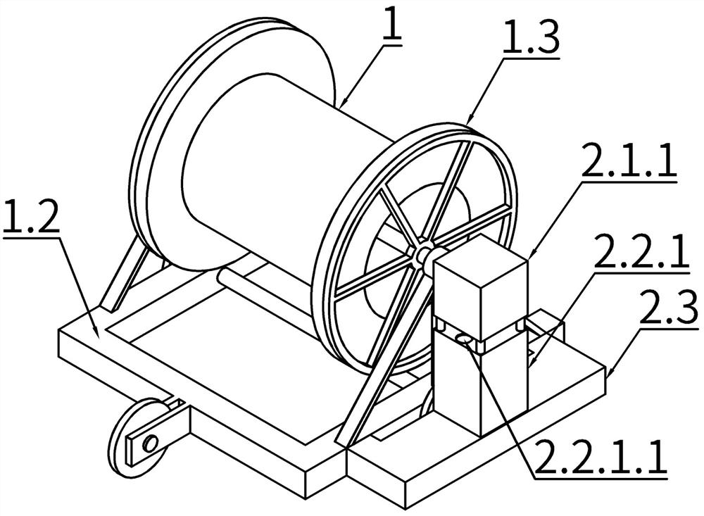
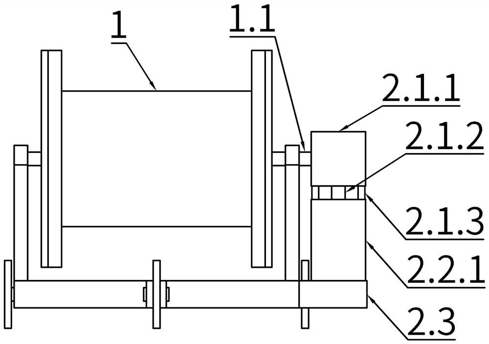
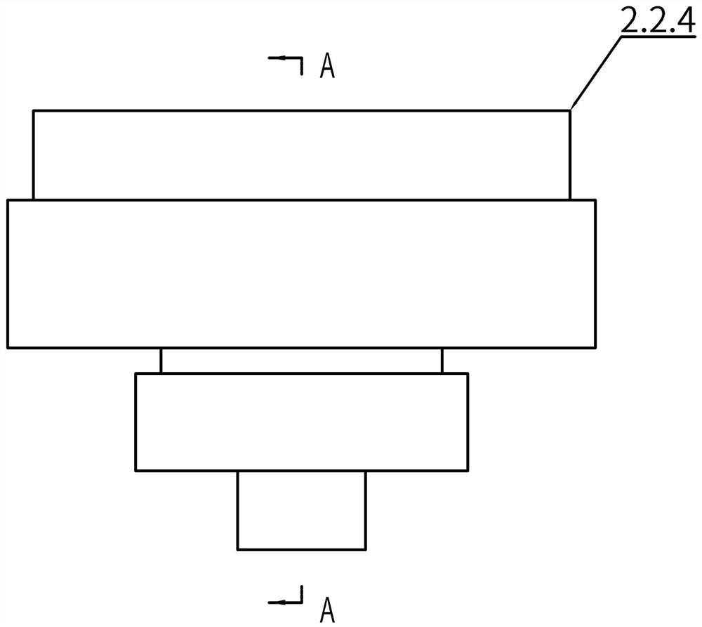
[0033] Such as Figure 1-12 shown. A tension pay-off device, comprising a pay-off barrel 1 placed on a vehicle frame 1.2, the pay-off barrel 1 is provided with a pay-off barrel rotation shaft 1.1 and a pay-off barrel rim 1.3 which rotate together with the pay-off barrel 1, and a There are buffer force generating device, support seat 2.3, and brake device (not shown in the figure); support seat 2.3 is used to support and fix the buffer force generating device; Apply a buffer force to the rotation of the pay-off drum rotating shaft 1.1; the buffer force generating device includes a buffer force generating device shell 2.2.1, and the buffer force generating device shell 2.2.1 is also provided with an air pressure through hole 2.2.1.1; the buffer force generating device Inside the casing 2.2.1, there is a buffer force generating cylinder 2.2.4 and a buffer force generating device piston 2.2.3 that can move axially along the buffer force generating cylinder 2.2.4, and the buffer f...

Embodiment 2

[0047] The difference between this embodiment and Embodiment 1 is that the power steering device support column 2.1.3 is no longer provided on the top of the buffer force generating device housing 2.2.1, but the power steering device housing is fixed on the vehicle frame 1.2 The end of the output shaft 2.1.2 of the power steering device is connected to the heavy block 2.1.4 through a rope, and the heavy block 2.1.4 is connected to the rotating part 2.2.2 of the buffer force generating device through a rope; there are 4 buffer force generating units, Correspondingly, the buffer force generating device piston 2.2.3 is also provided with first to fourth piston plates, thus, in H 1 = a, Z 2 = b, Z 3 = c, we know that H 2 = a, H 3 =a+b,H 4 =a+b+c. However, according to the structure disclosed in this embodiment, those skilled in the art can still easily know that the device disclosed in this embodiment can provide buffer force and thus relatively stable tension.


PUM


Abstract

The invention discloses a tension pay-off device. The tension pay-off device comprises a pay-off barrel arranged on a frame, the pay-off barrel is provided with a pay-off barrel rotating shaft and a pay-off barrel rim, the pay-off barrel rotating shaft and the pay-off barrel rotating shaft rotate together, and the tension pay-off device is further provided with a buffering force generating device, a supporting base and a brake device, the supporting base is used for supporting and fixing the buffering force generating device, the buffering force generating device is used for receiving power input by the pay-off barrel rotating shaft and applying buffering force to rotation of the pay-off barrel rotating shaft, the buffering force generating device comprises a buffering force generating device shell, an air pressure through hole is further formed in the buffering force generating device shell, a buffering force generating cylinder and a buffering force generating device piston capable of axially moving along the buffering force generating cylinder are arranged in the buffering force generating device shell, the tail end of the buffering force generating device piston extends out of the buffering force generating cylinder, and the brake device is pulled by the buffering force generating device piston to provide damping for a wheel rim of the pay-off barrel, so that the rotating speed of the pay-off barrel is controlled.

Description

technical field [0001] The invention belongs to the technical field of electric power laying equipment, and in particular relates to a tension pay-off device. Background technique [0002] Tension pay-off is an erection construction method that maintains a certain tension on the laid-out wires in the process of erecting the wires and keeps them off the ground in an overhead state. In layman's terms, one end of the wire and the ground wire is connected to the tension machine, and the other end is connected to the traction machine. The wire and the ground wire are released with a certain tension, and a certain height difference is maintained with the crossing object without friction, so as to avoid damage to the conductor and ground wire. ground wire. According to the latest line acceptance regulations, power line projects above 110kV must be tensioned, and optical cables or wires are not allowed to drag the floor during the process of setting out. In order to avoid the phen...

Claims


Application Information

Patent Timeline
Patent Type & Authority Applications(China)
IPC IPC(8): B65H59/04H02G1/04
CPCB65H59/04H02G1/04B65H2701/34B65H2701/32
Inventor 秦泽华王宏研于永泽王方苏郭楠伟孔真真
Owner STATE GRID CORP OF CHINA
Why Eureka
Try Eureka