
Sealing detection device and method

A sealing detection and sealing technology, applied in the field of sealing detection devices, can solve problems such as poor sealing detection effect of cup plating equipment, improve process stability and utilization rate, and avoid missed detection and false detection.

Pending Publication Date: 2021-07-16
ACM RES SHANGHAI
View PDF0 Cites 0 Cited by
  • Summary
  • Abstract
  • Description
  • Claims
  • Application Information

AI Technical Summary

Problems solved by technology

[0006] In view of the shortcomings of the prior art described above, the purpose of the present invention is to provide a sealing detection device and method for solving the problem of poor sealing performance of cup plating equipment in the prior art

Method used


Image

  • Sealing detection device and method
  • Sealing detection device and method
  • Sealing detection device and method

Examples


Embodiment 1

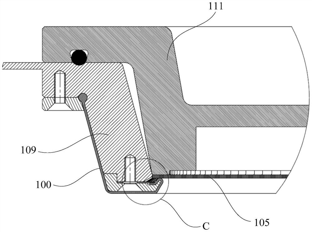
[0046] see Figure 1 to Figure 5 , the present embodiment provides a sealing detection device for detecting the sealing of the electroplating equipment seal 100, including:

[0047] The first electrode 101, the second electrode 102, the current detection module 103 and the judgment module 104;

[0048] Wherein, the current detection module 103 for detecting the current value is respectively connected to the first electrode 101 and the second electrode 102 through wires, and the judgment module 104 is connected to the current detection module 103 and obtains the current value ;

[0049] The surface of the substrate 105 clamped by the electroplating equipment is divided into a first area and a second area by the sealing member 100; the first electrode 101 is in contact with and connected to the first area, and the second electrode 102 is electroplated Liquid 106 connects the second region to form a detection loop between the first electrode 101, the substrate 105, the second e...

Embodiment 2

[0059] see Figure 1 to Figure 5 , the present embodiment provides a sealing detection method, comprising the following steps:

[0060] 1) The substrate 105 is loaded on the electroplating equipment, and the seal 100 of the electroplating equipment separates the surface of the substrate 105 into a first area not in contact with the electroplating solution 106 and a second area in contact with the electroplating solution 106;

[0061] 2) forming a detection circuit through the first region, the second region and the electroplating solution 106, energizing the detection circuit and detecting the actual current value of the detection circuit;

[0062] 3) Judging the tightness of the sealing member 100 to the electroplating solution 106 according to the actual current value.

[0063] In step 1), if Figure 1 to Figure 4 As shown, the substrate 105 is loaded on the electroplating equipment, and the seal 100 of the electroplating equipment separates the surface of the substrate 10...


PUM


Abstract

The invention provides a sealing detection device and method. The sealing detection device comprises a first electrode, a second electrode, a current detection module connected with the first electrode and the second electrode, and a judgment module connected with the current detection module; the surface of a base plate clamped by electroplating equipment is divided into a first area and a second area by a sealing piece, the first electrode is in contact connection with the first area, the second electrode is connected with the second area through electroplating liquid, and the first electrode, the base plate, the second electrode and the current detection module form a detection loop; and the current detection module is powered on to detect the actual current value of the detection loop, and the judgment module obtains the actual current value and judges the sealing performance of the sealing piece. According to the sealing detection device and method, the current detection module is introduced to detect the sealing performance of the sealing piece, so that automatic detection of the sealing performance of the sealing piece is realized, missing detection and false detection caused by visual detection in the prior art are avoided, and the process stability and operation rate of electroplating equipment are improved.

Description

technical field [0001] The invention relates to the field of semiconductor manufacturing equipment, in particular to a sealing detection device and method. Background technique [0002] In the integrated circuit manufacturing process, the metal plating process is widely used due to its good uniformity and applicability. In addition to the copper interconnect structure in the back-end process, metal plating processes have also been widely used in the advanced wafer-level packaging field, such as copper pillars, RDL (redistribution layer), TSV and interposer boards. [0003] At present, there are two types of electroplating equipment on the market: horizontal jet cup plating and vertical rack plating. Among them, rack plating is to immerse the wafer vertically in the plating solution, and one plating tank can perform electroplating on multiple pieces at the same time. Cup plating is to cover the wafer in a cup-shaped plating tank, and the electroplating process is carried ou...

Claims


Application Information

Patent Timeline
Patent Type & Authority Applications(China)
IPC IPC(8): C25D17/00C25D21/12
CPCC25D17/004C25D21/12
Inventor 贾照伟盛俊威王坚王晖
Owner ACM RES SHANGHAI
Learn More