Eureka AIR delivers breakthrough ideas for toughest innovation challenges, trusted by R&D personnel around the world.

Flow regeneration characteristic test system and test method

A technology of characteristic test and flow regeneration valve, applied in fluid pressure actuation system test, fluid pressure actuation device, mechanical equipment and other directions, can solve the problems of high cost and long test time, and achieve high cost, long test time, Time and cost saving effect

Active Publication Date: 2021-07-16
ZOOMLION HEAVY IND CO LTD
View PDF9 Cites 0 Cited by
  • Summary
  • Abstract
  • Description
  • Claims
  • Application Information

AI Technical Summary

Problems solved by technology

[0004] The purpose of the embodiment of the present invention is to provide a flow regeneration characteristic test system and test method, which solves the problems of high cost and long test time in the flow regeneration characteristic test method in the prior art. This application adopts multiple target pressure values, Correspondingly control the input pressures of multiple working oil ports of the flow regeneration valve to be measured, and detect in real time whether the multiple target pressure values ​​are consistent with the multiple feedback pressure values ​​of the corresponding multiple working oil ports, and when the multiple target pressure values When the pressure value is consistent with the corresponding plurality of feedback pressure values, the difference between the first flow outflow from the designated working oil port among the plurality of working oil ports and the second flow rate flowing in from the oil inlet port of the regeneration valve to be measured is calculated. The difference between them is determined as the regeneration flow rate corresponding to the target pressure value of the flow rate regeneration valve to be measured, which realizes the simple switching of various main engine cylinder working conditions, saving time and cost

Method used


Image

  • Flow regeneration characteristic test system and test method
  • Flow regeneration characteristic test system and test method
  • Flow regeneration characteristic test system and test method

Examples


Embodiment Construction

[0041] The specific implementation manners of the embodiments of the present invention will be described in detail below in conjunction with the accompanying drawings. It should be understood that the specific implementation manners described here are only used to illustrate and explain the embodiments of the present invention, and are not intended to limit the embodiments of the present invention.

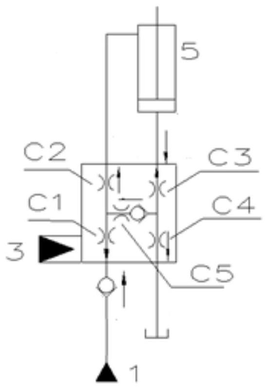
[0042] figure 1 It is the schematic diagram of the simplified flow regeneration characteristic test. Such as figure 1 As shown, the output flow q of the hydraulic pump 1 p1 All flows into the flow regeneration chamber, that is, the rod chamber of the loading cylinder 5, and then flows out from another chamber of the loading cylinder 5, that is, the rodless chamber of the loading cylinder 5, the flow rate q bAfter passing through the regeneration check valve in the flow regeneration valve 3, it is divided into two paths. One path flows into the rod cavity of the loading cylinder...


PUM


Abstract

The invention relates to the technical field of hydraulic transmission, and discloses a flow regeneration characteristic test system and a test method, which aim to solve the problems of high cost and long test time in a flow regeneration characteristic test way in the prior art. The method comprises the following steps: obtaining a plurality of target pressure values, and respectively and correspondingly controlling input pressure of a plurality of working oil ports of a to-be-tested flow regeneration valve; detecting whether the plurality of target pressure values are consistent with a plurality of feedback pressure values of the corresponding working oil ports in real time; obtaining first flow flowing out from a specified working oil port among the plurality of the working oil ports and second flow flowing into an oil inlet; and determining a difference value between the first flow and the second flow as regeneration flow corresponding to the target pressure values of the to-be-detected flow regeneration valve. The flow regeneration characteristic test system is suitable for a regeneration flow determining process of the flow regeneration valve.

Description

technical field [0001] The invention relates to the technical field of hydraulic transmission, in particular to a flow regeneration characteristic test system and test method. Background technique [0002] Flow regeneration means that when the direction of movement of the actuator is the same as that of the load force (that is, negative load), the pressure generated by the load is used to transport the oil from the high-pressure chamber to the low-pressure chamber, so that the flow rate of the main pump required by the system is minimum or zero. The flow regeneration characteristic test is an effective method to evaluate the flow regeneration oil supply rate. There are two methods for the current flow regeneration characteristic test method, one is to carry out the hydraulic valve flow regeneration characteristic test on the actual vehicle, and the other is to design The special test platform for the oil cylinder loading method, but the essence of the above two is to use th...

Claims


Application Information

Patent Timeline
Patent Type & Authority Applications(China)
IPC IPC(8): F15B19/00
CPCF15B19/007
Inventor 袁野张军花王维张瑞鑫周启迪张劲
Owner ZOOMLION HEAVY IND CO LTD
Why Eureka
Eureka Blog
Learn More