

Automatic pressure relief valve and data disaster recovery storage device including the same
A storage device and automatic leakage technology, applied in valve devices, reducing physical parameters of carriers, balancing valves, etc., can solve problems such as poor heat resistance and durability, achieve precise temperature control protection, ensure data security, and anti-corrosion data security. Effect
- Summary
- Abstract
- Description
- Claims
- Application Information
AI Technical Summary
Problems solved by technology
Method used
Image

Examples
Embodiment 1
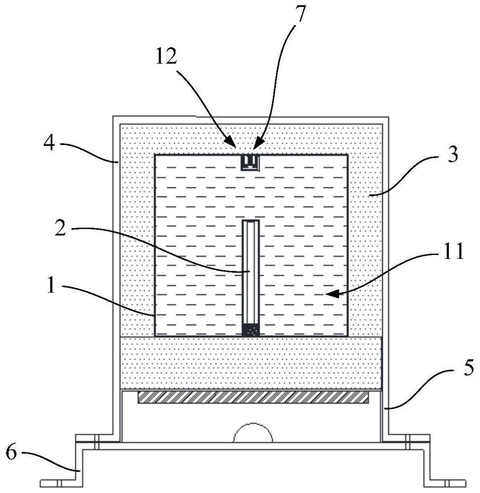
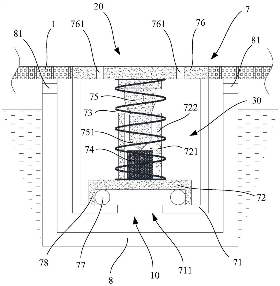
[0070] like figure 1 and figure 2 Shown is Embodiment 1 of the present invention. This embodiment provides a data disaster recovery storage device. The data disaster recovery storage device includes an inner tank 1 with a hollow cavity 11. The hollow cavity 11 is filled with cooling liquid, and the cooling liquid is surrounded by data memory 2. Specifically in this embodiment, the outer wall of the inner pot 1 is recessed inward to form a groove for accommodating the data storage device 2 , that is, the wall of the groove is integrally connected with the wall of the inner pot 1, specifically by welding, or sheet metal stamping, Alternatively, the above structure can be realized by means of flange mounting, which is not limited in the present invention. With this structure, the data storage device 2 can be installed outside the inner tank 1 without affecting the protection of the data storage device 2 by the cooling liquid.
[0071] The inner pot 1 has an opening 12, and co...
Embodiment 2
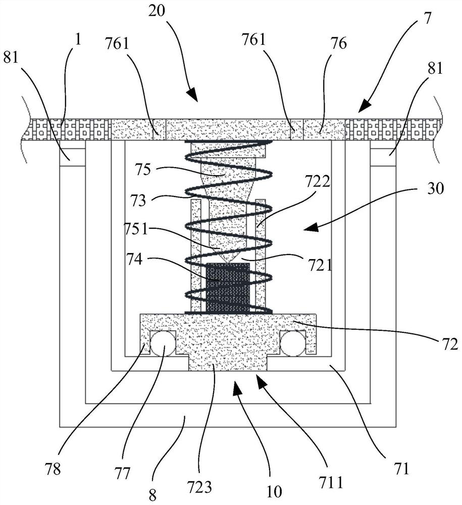
[0089] like image 3 Shown is Embodiment 2 of the present invention. The automatic pressure relief valve provided in this embodiment is basically the same as the automatic pressure relief valve in Embodiment 1. The difference is that in this embodiment, the movable member 72 is provided with a direction The pressure relief hole 711 has a protruding plunger 723 , and the plunger 723 cooperates with the pressure relief hole 711 to improve the sealing performance of the pressure relief hole 711 . When the pressure difference causes the plunger 723 to escape from the pressure relief hole 711 , the pressure relief hole 711 is opened, and the high temperature and high pressure steam can be discharged through the pressure relief hole 711 . In this embodiment, the pressure relief hole 711 is completely filled by the plunger 723, thereby ensuring that the pressure relief hole 711 is sealed.
Embodiment 3
[0091] like Figure 4 Shown is Embodiment 3 of the present invention. The automatic pressure relief valve provided in this embodiment is basically the same as the automatic pressure relief valve in Embodiment 2. The difference is that in this embodiment, the length of the plunger 723 is shorter , when the movable member 72 is in the first position, only part of the pressure relief hole 711 is filled by the plunger 723, so the movable member 72 is lifted up a short distance so that the pressure relief hole 711 can discharge high temperature and high pressure steam. In addition, the end of the plunger 723 is provided with a chamfer, so when the movable member 72 moves from the second position to the first position, the plunger 723 can easily enter the pressure relief hole 711 to prevent the plunger 723 from being stuck in the pressure relief hole Outside the hole 711, no sealing can be achieved.
PUM
| Property | Measurement | Unit |
|---|---|---|
| diameter | aaaaa | aaaaa |
| melting point | aaaaa | aaaaa |
Abstract
Description
Claims
Application Information