Forming limit testing method

A technology of forming limit and testing method, applied in special data processing applications, geometric CAD, design optimization/simulation, etc., can solve the problems of difficulty in printing precise meshes, low efficiency, and inability to accurately reflect the forming limit, etc. The effect of experimental efficiency, wide control range and reliable judgment results

Active Publication Date: 2021-07-16
TONGJI UNIV
View PDF6 Cites 2 Cited by
  • Summary
  • Abstract
  • Description
  • Claims
  • Application Information

AI Technical Summary

Problems solved by technology

The main difficulties that this method often faces when testing ultra-thin metal plate substrate FLD are: 1. The thickness of the ultra-thin metal plate substrate is usually 0.05-0.1mm, and the characteristic size of the plate is usually below 1mm. It is difficult to print a precise grid (such as a diameter of less than 0.2mm) on a metal sheet; 2. The size (diameter or side length) of the sample used in the Nakazima and Marciniak tests is 180mm, and the test results cannot accurately reflect ultra-thin metal poles. Forming limit of small-scale forming (≤1mm) of plate substrate; 3. Traditional forming limit test method, one test can only obtain data under one strain path, and obtaining a complete forming limit diagram requires a large number of tests, which is inefficient

Method used


Image

  • Forming limit testing method
  • Forming limit testing method
  • Forming limit testing method

Examples


Embodiment Construction

[0044] The implementation of the present invention will be illustrated by specific specific examples below, and those skilled in the art can easily understand other advantages and effects of the present invention from the contents disclosed in this specification.

[0045]It should be noted that the structures, proportions, sizes, etc. drawn in the drawings of this specification are only used to match the content disclosed in the specification, for those who are familiar with this technology to understand and read, and are not used to limit the conditions for the implementation of the present invention. Therefore, there is no technical substantive meaning, and any modification of structure, change of proportional relationship or adjustment of size shall still fall within the scope of the disclosure of the present invention without affecting the functions and objectives of the present invention. within the scope of technical content. At the same time, terms such as "upper", "low...


PUM


Abstract

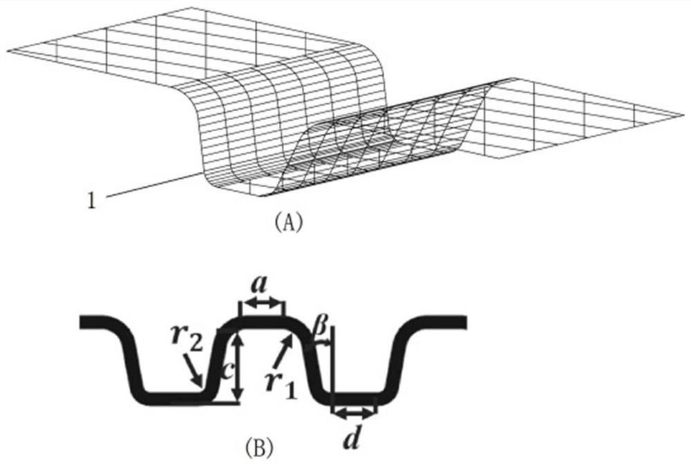
The invention relates to a forming limit testing method which comprises the following steps: S1, designing a stamping deformation structure on a metal pole plate, including three types of a straight runner structure, a circular truncated cone structure and a bulging structure, and determining critical dimension parameters; s2, respectively selecting values of an upper bend inner circle radius r1 and a lower bend inner circle radius r2 as calculation base values, selecting a plurality of groups of key dimension parameters, and obtaining a maximum thinning rate through finite element simulation; determining the ratio alpha of the secondary strain to the main strain; s3, using a stamping device for stamping on the sample plate to form a corresponding stamping deformation structure, and obtaining a forming limit sample; s4, performing section observation and measurement on the stamping deformation structure on the forming limit sample, judging whether cracking or necking or local thinning occurs or not, obtaining a strain parameter set through calculation, and obtaining a cracking point, a necking or local thinning point and a safety point; and S5, drawing all the cracking points, the necking or local thinning points and the safety points to obtain a forming limit diagram.

Description

technical field [0001] The invention relates to the field of formability testing of thin metal plate materials, in particular to a formability limit test method. Background technique [0002] The forming limit is a quantitative description of the formability of the sheet metal. Accurately characterizing the forming limit is the key to solving the sheet metal stamping problem and judging the quality of the stamping process, which is of great significance to the optimization of the stamping process. Forming limit diagrams are usually used to characterize the forming limit of the sheet metal. The forming limit curve is obtained by connecting the forming limit points of the sheet metal under various stress states into a curve, and the forming limit curve is drawn in the strain space, which is called the forming limit diagram. [0003] The current test method for obtaining the forming limit diagram of sheet metal is to test according to the national standard: GB / T15825.8-2008 "Fo...

Claims


Application Information

Patent Timeline
Patent Type & Authority Applications(China)
IPC IPC(8): G06F30/17G06F30/23
CPCG06F30/17G06F30/23
Inventor 闵峻英明平文张存满杨代军郭楠
Owner TONGJI UNIV
Why Eureka
Try Eureka