Stator winding structure and electric machine comprising stator winding structure

A stator winding and winding technology, applied in the shape/style/structure of winding conductors, windings, electromechanical devices, etc., can solve the problems of electromagnetic coupling uneven current circulation, etc., to reduce current circulation, improve heat dissipation capacity, and reduce heat radiation Effect

Active Publication Date: 2022-06-21
SAIC MOTOR
View PDF5 Cites 0 Cited by
  • Summary
  • Abstract
  • Description
  • Claims
  • Application Information

AI Technical Summary

Problems solved by technology

[0008] Aiming at the problem of current circulation caused by uneven electromagnetic coupling caused by magnetic flux leakage in 6-pole multi-layer (6 layers and above) flat copper wire windings widely used at present, the present invention proposes a winding structure with 6 branches in parallel

Method used


Image

  • Stator winding structure and electric machine comprising stator winding structure
  • Stator winding structure and electric machine comprising stator winding structure
  • Stator winding structure and electric machine comprising stator winding structure

Examples


Embodiment 1

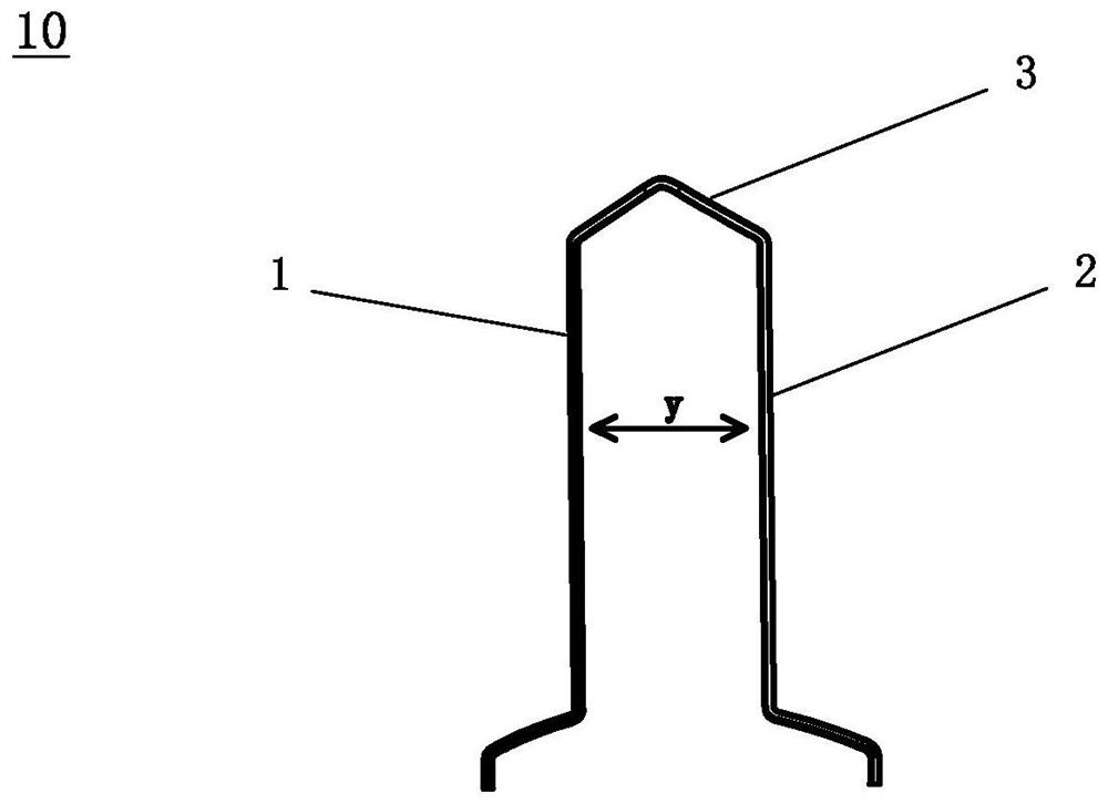
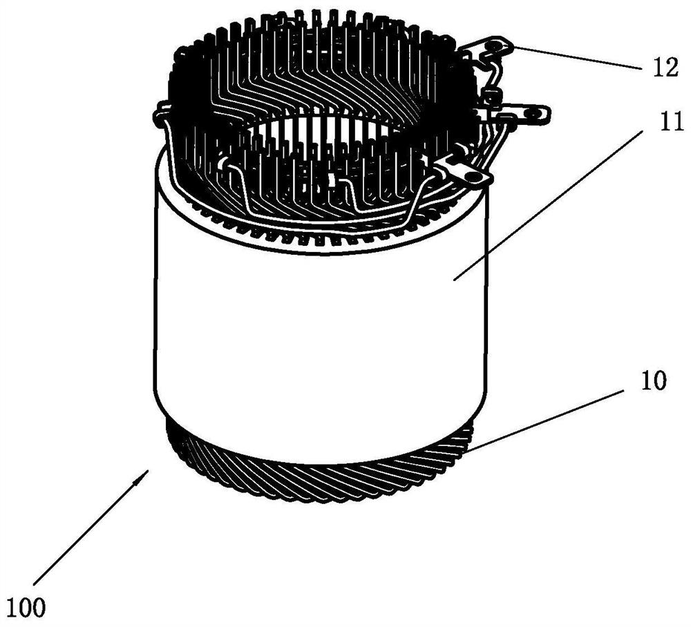
[0147] In the three-phase AC motor of this example, the stator includes a stator core 11 and a stator winding structure 100 . The stator core 11 has a plurality of slots distributed in the circumferential direction. The stator winding structure 100 is composed of a plurality of U-shaped flat copper wires 10 .

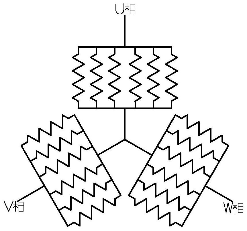
[0148] Three-phase (U, V and W phases) outgoing wires in the stator are arranged at the welding ends of the U-shaped flat copper wires 10 of the stator winding structure 100 . Accordingly, the deflector 12 (eg Figures 7A-7C Its internal wiring is shown in detail) is also arranged at the welding end for the outgoing wires of each phase. The stator of the first embodiment is as Figure 3-4 shown.

[0149] like Figure 5-6 , Figures 8A-8F as well as Figures 9A-9F As shown, the perspective view, the wiring structure diagram and the developed view from the U-shaped end (the first side) of the six parallel-wound branches of the U-phase winding 100U of the first embo...

Embodiment 2

[0172] In the three-phase AC motor of this example, the stator includes a stator core 11 and a stator winding structure 100 . The stator core 11 has a plurality of slots distributed in the circumferential direction. The stator winding structure 100 is composed of a plurality of U-shaped flat copper wires 10 .

[0173] Three-phase (U, V and W phases) outgoing wires in the stator are arranged at the U-shaped ends of the U-shaped flat copper wires 10 of the stator winding structure 100 . Accordingly, the deflector 12 (eg Figures 7A-7C Its internal wiring is shown in detail in ) is also arranged at the U-shaped end for the outgoing wires of each phase. The stator of the second embodiment is as Figure 10-11 shown.

[0174] like Figure 12-13 , Figures 14A-14F as well as Figures 15A-15F As shown, the perspective view, the wiring structure diagram and the developed view from the U-shaped end (the first side) of the six parallel-wound branches of the U-phase winding 100U of...


PUM


Abstract

The present application provides a stator winding structure for a motor, the motor is a three-phase AC motor with six poles, each phase includes six parallel winding branches, the stator winding is composed of a plurality of U-shaped flat copper wires, The connecting parts of each U-shaped flat copper wire are located on the same side relative to the motor. The present application also provides an electric machine including a stator winding structure and a vehicle including the electric machine. The stator winding structure has the advantages of improving the heat dissipation capacity of the conductors away from the cooling liquid in the stator slot, balancing the temperature difference between the conductors of each layer, and the like.

Description

technical field [0001] The present application relates to a stator winding structure and a motor including the stator winding structure, in particular to a stator winding structure constructed of flat wires, and the motor including the stator winding can be used as a drive motor or a generator to be suitable for new energy vehicles and the like. Background technique [0002] Electric machines, such as AC motors, include stator assemblies and rotor assemblies. The stator assembly generally includes a stator winding and a stator core. The stator winding provides the electrical energy input and the establishment of the magnetic field for the motor, while the stator core provides the magnetic load channel for the motor. [0003] In order to improve the power density of the motor, enhance the heat dissipation capacity and structural stability of the motor, etc., the motors used in new energy vehicles often use hairpin flat wire windings, which greatly improves the slot full rate...

Claims


Application Information

Patent Timeline
Patent Type & Authority Patents(China)
IPC IPC(8): H02K3/28H02K3/12H02K3/50
CPCH02K3/28H02K3/12H02K3/50
Inventor 王健黄少锐李节宝李灏淳
Owner SAIC MOTOR
Why Eureka
Try Eureka