A two-way magnetic projection automatic separation device for plastic waste

A separation device and waste technology, which is applied in the field of plastic waste two-way magnetic projection automatic separation device, can solve the problems of reduced separation accuracy, small amount of single separation, and inability to meet the separation needs of large quantities of plastic waste, etc., to achieve reduction Efficiency, reduction of separation cost, effect of increase of separation cost

Active Publication Date: 2022-05-06
ZHEJIANG UNIV
View PDF7 Cites 0 Cited by
  • Summary
  • Abstract
  • Description
  • Claims
  • Application Information

AI Technical Summary

Problems solved by technology

[0005] However, the single separation volume of the above-mentioned separation device is small. When the separation volume is large, the initial movement points of all wastes in the sample delivery channel are different due to the horizontal repulsion force of the magnet, resulting in a decrease in separation accuracy, which cannot meet the separation needs of large quantities of plastic waste.

Method used


Image

  • A two-way magnetic projection automatic separation device for plastic waste
  • A two-way magnetic projection automatic separation device for plastic waste
  • A two-way magnetic projection automatic separation device for plastic waste

Examples


Embodiment Construction

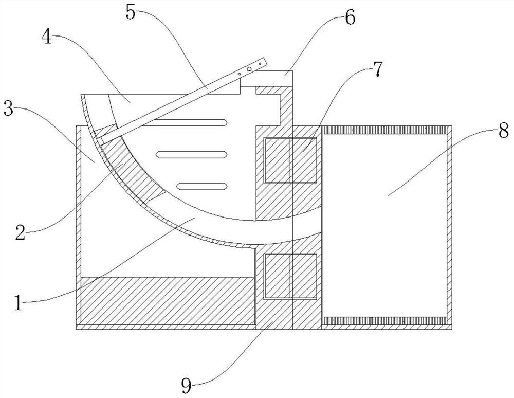
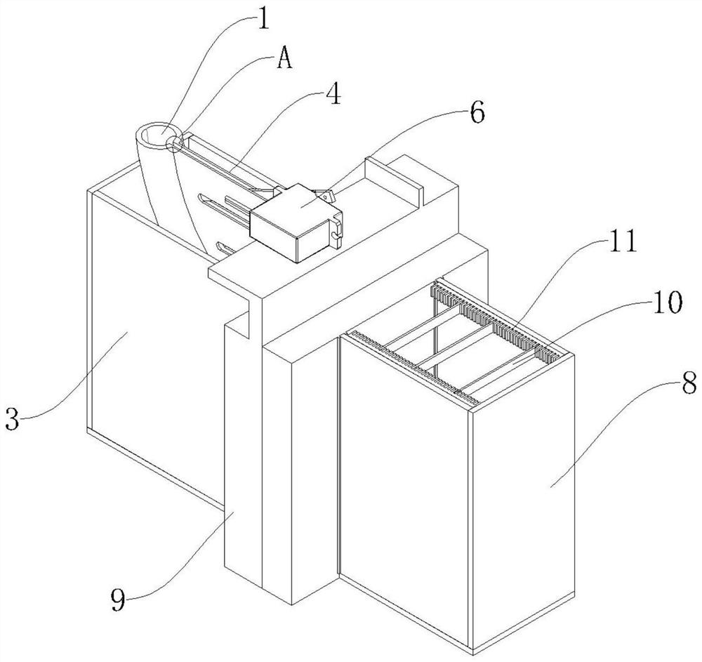
[0066] Such as Figure 1-5 As shown, the plastic waste two-way magnetic projection automatic separation device proposed by the present invention includes a feeding mechanism, a separation box and two ring magnets that are both axially magnetized;

[0067] The feeding mechanism includes a feeding box 3, a feeding channel 1 and a pendulum 2; two ring magnets 7 are arranged coaxially, and their central axes are arranged horizontally, and are installed on the feeding box 3 and the separation box 8 through two detachable cover plates 9 Between; separation box 8 is equipped with paramagnetic medium solution.

[0068] The feed channel 1 includes a feed section and a discharge section, and the discharge section communicates with a separation box 8 . The opposite sides of the two cover plates 9 are respectively provided with annular placement grooves 12 , and the ring magnets 7 are installed in the annular placement grooves 12 . A cylindrical protrusion is formed in the middle of the...


PUM

PropertyMeasurementUnit
thicknessaaaaaaaaaa
thicknessaaaaaaaaaa
densityaaaaaaaaaa

Abstract

The invention provides an automatic bidirectional magnetic projection separation device for plastic waste, which includes a separation box for holding a medium solution; a feeding mechanism and an axially magnetized annular magnet group arranged between the feeding mechanism and the separation box; The mechanism includes a feed channel through which the discharge end passes through the ring magnet group and communicates with the separation box, and a pendulum that is slidably arranged in the feed channel and can push the materials in the feed channel to the separation box; the end surface of the discharge end of the feed channel and the ring The direction of the central axis of the magnet group is vertical; the end surface of the pushing end of the pendulum has a profile structure consistent with the end surface of the discharging end; the center of the end surface of the discharging end is close to or located at the central axis of the ring magnet group. The automatic separation device of the present invention has high separation accuracy, high separation recovery rate, large single separation amount, and can separate a mixture of various plastic wastes, greatly improving work efficiency and reducing separation cost.

Description

technical field [0001] The invention belongs to the technical field of separation of plastic waste, and in particular relates to a bidirectional magnetic projection automatic separation device for plastic waste. Background technique [0002] Plastic is widely used in daily life and industrial production because of its advantages of easy shaping, light weight, high fatigue strength, and corrosion resistance, but it also generates a lot of plastic waste. At the same time, plastic waste is usually characterized by a high degree of mixing, various types, and large quantities, making it difficult to recycle reasonably and efficiently. The high cost of separation of plastic waste and low separation efficiency are the main difficulties in the recycling of plastic waste. [0003] In order to deal with the separation and recycling of different plastics, there are currently more discussions on foam separation, hydrocyclone separation and electrostatic separation. The froth flotation...

Claims


Application Information

Patent Timeline
Patent Type & Authority Patents(China)
IPC IPC(8): B29B17/02
CPCB29B17/02B29B2017/0203B29B2017/0244Y02W30/62Y02W30/52
Inventor 赵朋戴煌哲张雪纯张伟桐张承谦颉俊郑建国傅建中
Owner ZHEJIANG UNIV
Why Eureka
Try Eureka