Efficient highway crack treatment device for highway engineering
A treatment device and road technology, applied in the direction of roads, roads, road repairs, etc., can solve the problems of low dust collection efficiency, concentration, and poor cleaning effect, and achieve the effect of comprehensive cleaning, good cleaning effect, and convenient washing
- Summary
- Abstract
- Description
- Claims
- Application Information
AI Technical Summary
Problems solved by technology
Method used
Image
Examples
Embodiment 1
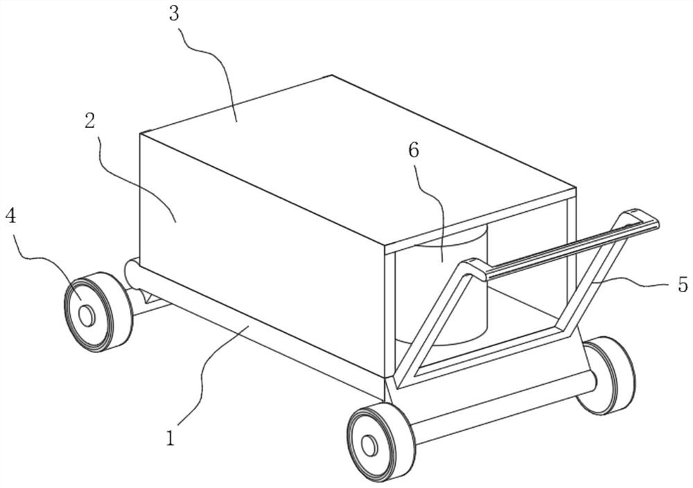
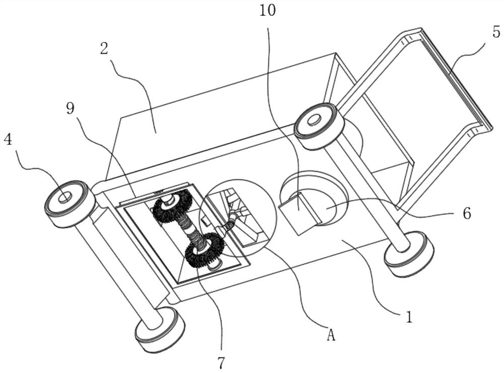
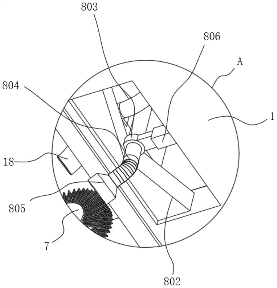
[0030] see Figure 1-7 , the present invention provides a technical solution: a high-efficiency road crack treatment device for road engineering, comprising a bottom plate 1, the top of the bottom plate 1 is fixedly connected with a vertical plate 2, and the top of the vertical plate 2 is movably connected with a top plate 3, and the top of the bottom plate 1 The four corners of the bottom are movably connected with rollers 4, the right side of the bottom plate 1 is fixedly connected with a push handle 5, one side of the bottom plate 1 is fixedly connected with a discharge bucket 6, one side of the bottom plate 1 is provided with a cleaning device 7, and the top of the bottom plate 1 is located The left side of the discharge barrel 6 is fixedly connected with a comprehensive spraying device 8, and the inside of the base plate 1 is provided with a leak hole 9, and the top of the base plate 1 is fixedly connected with a water tank 15 on the right side of the comprehensive sprayin...
Embodiment 2
[0034] see Figure 1-7 As shown, on the basis of Embodiment 1, the present invention provides a technical solution: the cleaning device 7 includes a horizontal plate 701, the top of the horizontal plate 701 is fixedly connected with a motor one 702, and one side of the motor one 702 is rotatably connected with a cam 703 The bottom of the cam 703 is provided with a moving plate 704, the bottom of the moving plate 704 is fixedly connected with a moving frame 705, the outer wall of the moving frame 705 is fixedly connected with a slide plate 706, and the inner wall of one side of the moving frame 705 is fixedly connected with a motor 2 707, and the motor 2 One side of 707 is connected with gear one 708, the bottom of gear one 708 is meshed with gear two 709, one side of gear two 709 is connected with two-way screw 710, and the outer wall of two-way screw 710 is connected with cleaning brush 711 and slide plate 706. The outer wall is slidingly connected with the inner wall of the ...
Embodiment 3
[0037] see Figure 1-7 As shown, on the basis of Embodiment 1 and Embodiment 2, the present invention provides a technical solution: the bottom of the discharge barrel 6 is hinged with a discharge plate 10, and the left side of the discharge plate 10 is provided with a groove 11. The right side inner wall of groove 11 is fixedly connected with extension spring 12, and the left side of extension spring 12 is fixedly connected with slide block 13, and the top of slide block 13 is hinged with hydraulic cylinder 14, and the top of hydraulic cylinder 14 is connected with the discharge barrel 6. The bottom outer wall is hinged.
[0038] In this embodiment, the discharge plate 10 provided is used to discharge the repair fluid inside the discharge barrel 6. When the hydraulic cylinder 14 is activated, the slide block 13 moves accordingly. At this time, the tension spring 12 gradually stretches and Automatically reset, then the discharge plate 10 is convenient to rotate up and down, t...
PUM
 Abstract
Description
Claims
Application Information
 - R&D
- Intellectual Property
- Life Sciences
- Materials
- Tech Scout
- Unparalleled Data Quality
- Higher Quality Content
- 60% Fewer Hallucinations
Browse by: Latest US Patents, China's latest patents, Technical Efficacy Thesaurus, Application Domain, Technology Topic, Popular Technical Reports.
© 2025 PatSnap. All rights reserved.Legal|Privacy policy|Modern Slavery Act Transparency Statement|Sitemap|About US| Contact US: help@patsnap.com


