
Noise insulation barrier structure for road construction

A road construction and barrier technology, applied in the direction of noise absorption device, fence, building type, etc., can solve the problems of increasing labor intensity, stacking stones, and bulky barrier structure, avoiding inconvenient installation, reducing labor intensity, The effect of improving flexibility

Inactive Publication Date: 2021-07-20
齐勤华
View PDF0 Cites 1 Cited by
  • Summary
  • Abstract
  • Description
  • Claims
  • Application Information

AI Technical Summary

Problems solved by technology

[0003] At present, there are still some deficiencies in the existing road construction noise barrier structure, for example; the existing road construction noise barrier structure cannot be retracted and folded when not in use, and the volume of the barrier structure is relatively large during transportation. In order to reduce the labor intensity of the operator during the handling process, the barrier structure is prone to bumps during the handling process, and the existing road construction noise barrier structure cannot directly stack stones on the load-bearing plate, so that the barrier structure can be fixed. It is necessary to use ground piles to fix the load-bearing plate, which increases the installation time of the barrier structure, reduces the convenience of the barrier structure in the disassembly process, and cannot directly install the barrier structure in an arc, which limits the barrier structure. When the road is isolated, the barrier structure is prone to inconvenient installation at the bend, which reduces the flexibility of the barrier structure during use

Method used


Image

  • Noise insulation barrier structure for road construction
  • Noise insulation barrier structure for road construction
  • Noise insulation barrier structure for road construction

Examples


Embodiment Construction

[0027] The technical solutions in the embodiments of the present invention will be clearly and completely described below with reference to the accompanying drawings in the embodiments of the present invention. Obviously, the described embodiments are only a part of the embodiments of the present invention, but not all of the embodiments.

[0028] In the description of the present invention, it should be understood that the terms "upper", "lower", "front", "rear", "left", "right", "top", "bottom", "inside", " The orientation or positional relationship indicated by "outside" is based on the orientation or positional relationship shown in the accompanying drawings, and is only for the convenience of describing the present invention and simplifying the description, rather than indicating or implying that the indicated device or element must have a specific orientation, so as to The specific orientation configuration and operation are therefore not to be construed as limitations of...


PUM


Abstract

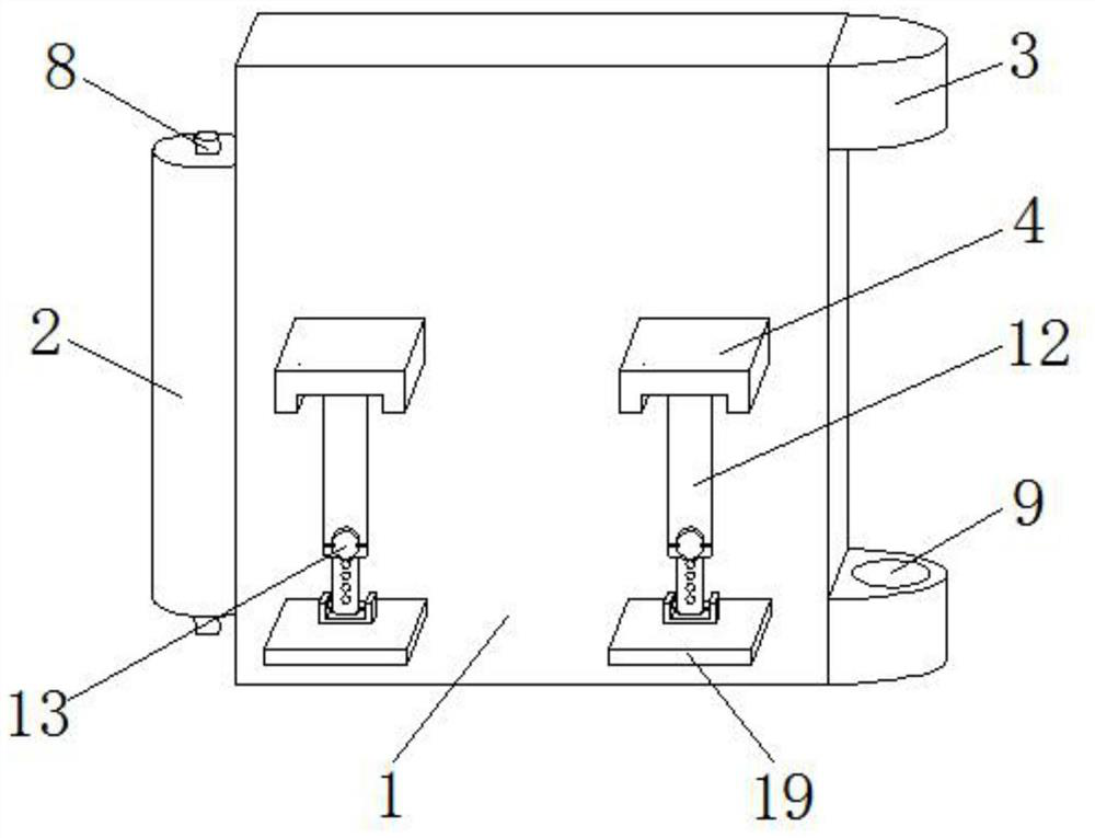
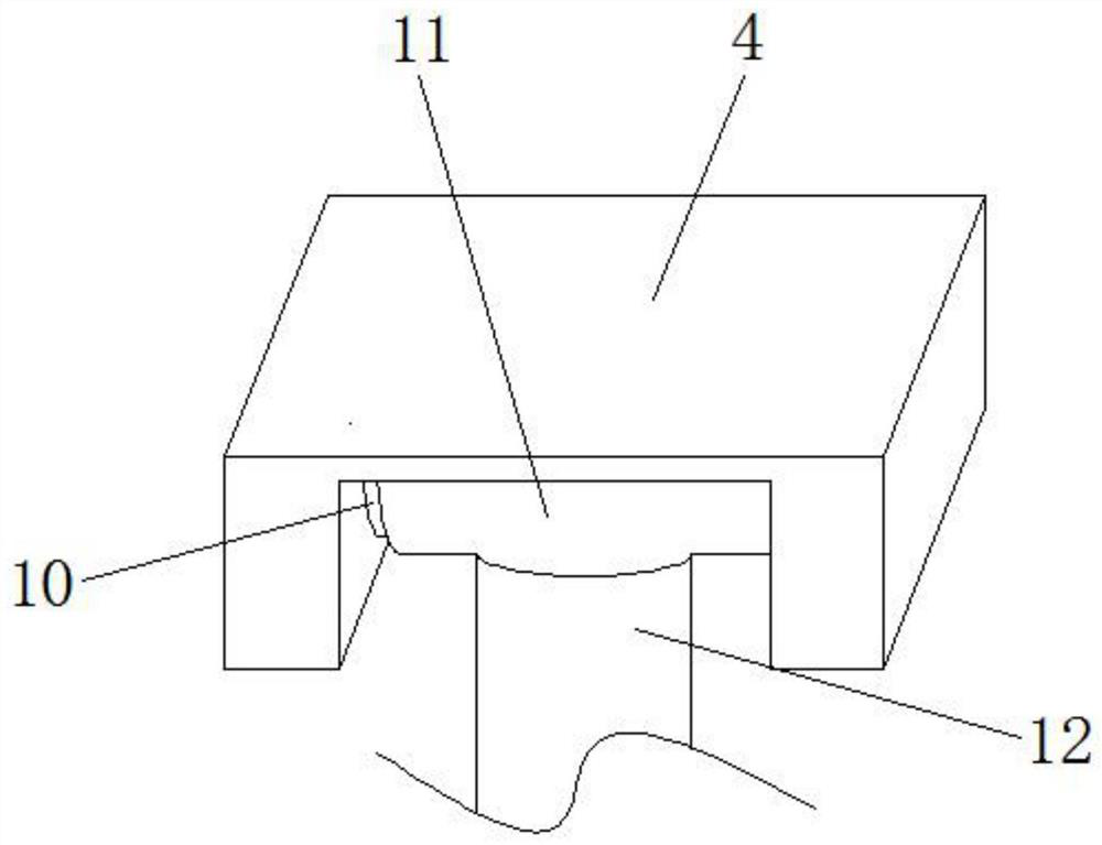
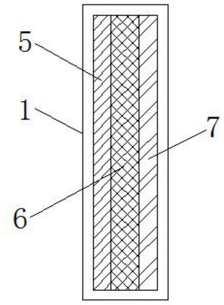
The invention discloses a sound insulation barrier structure for road construction. The sound insulation barrier structure for road construction structurally comprises a barrier plate, wherein a fixing column, connecting plates, fixing plates, a first sound insulation layer, a second sound insulation layer and a third sound insulation layer are arranged on the barrier plate; the fixing column is welded to the left end of the barrier plate; the connecting plates are welded to the right end of the barrier plate, and are symmetrically arranged at the upper side and the lower side of the barrier plate; the fixing plates are welded to the outer surface of the barrier plate; the first sound insulation layer is positioned at the left side of the inside of the barrier plate; the second sound insulation layer is positioned in the middle of the inside of the barrier plate; the third sound insulation layer is positioned at the right side of the inside of the barrier plate; and an embedding column is fixedly arranged on the fixing column. The barrier structure can be contracted and folded when not being used, the size of the barrier structure in the transportation process is reduced, the labor intensity of operators in the carrying process is reduced, and the phenomenon that the barrier structure is collided in the carrying process is avoided.

Description

technical field [0001] The invention relates to the technical field of road construction, in particular to a noise barrier structure for road construction. Background technique [0002] In daily life, there are often cases of road besieging and construction, and there will also be construction noise. In order not to affect the lives of nearby people, the current method is often to stop construction at night. [0003] At present, the existing road construction noise barrier structures still have some deficiencies. For example, the existing road construction noise barrier structures cannot be folded and folded when not in use. It reduces the labor intensity of the operator during the handling process, and the barrier structure is prone to bumping during the handling process, and the existing road construction noise barrier structure cannot directly stack stones on the load-bearing plate, so that the barrier structure can be fixed. It is necessary to use ground piles to fix th...

Claims


Application Information

Patent Timeline
Patent Type & Authority Applications(China)
IPC IPC(8): E04H17/16E04H17/20E01F8/00
CPCE01F8/0017E01F8/0023E04H17/16E04H17/20
Inventor 齐勤华
Owner 齐勤华
Learn More