Drilling fluid chemical osmotic pressure difference testing device

A technology of chemical osmosis and testing equipment, applied in measuring equipment, permeability/surface area analysis, measurement, etc., can solve problems such as distortion of experimental results, difficult operation, difficult measurement of osmotic pressure changes, etc., to achieve wide application range and accurate experimental results , the effect of easy installation

Inactive Publication Date: 2021-07-20
SOUTHWEST PETROLEUM UNIV
View PDF1 Cites 0 Cited by
  • Summary
  • Abstract
  • Description
  • Claims
  • Application Information

AI Technical Summary

Problems solved by technology

[0005] The problem with the above-mentioned test device is that the above-mentioned test device does not have a specific instrument that can directly measure the osmotic pressure change, making it difficult to directly and obviously measure the osmotic pressure change between the drilling fluid and the formation water; For the wall of the core barrel, when the above-mentioned device is used for testing, the drilling fluid and water will be exchanged through the gap between the core barrel and the core, resulting in serious distortion of the final measured experimental results, and it is also difficult to place the core in the It is difficult to operate between core barrels

Method used


Image

  • Drilling fluid chemical osmotic pressure difference testing device
  • Drilling fluid chemical osmotic pressure difference testing device

Examples


Embodiment Construction

[0021] In order to have a clearer understanding of the technical features, purposes and beneficial effects of the present invention, the technical solution of the present invention is described in detail below, but it should not be construed as limiting the scope of implementation of the present invention.

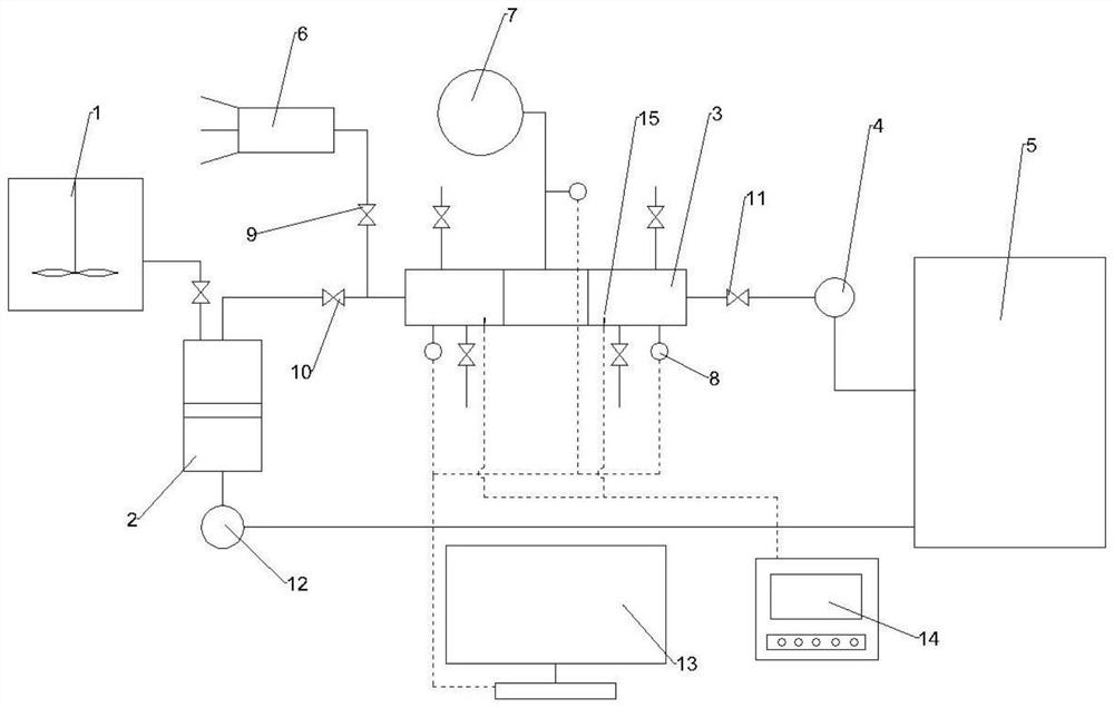
[0022] A drilling fluid chemical osmotic pressure difference testing device, comprising a drilling fluid tank 1, an intermediate container 2, an experimental cylinder 3, a first constant pressure pump 4 and a formation water tank 5 connected in sequence, and the formation water tank 5 is also connected with a second constant pressure The pressure pump 12; the intermediate container 3 is composed of a drilling fluid chamber, a piston and a water chamber. The drilling fluid chamber is provided with a drilling fluid inlet pipe and a drilling fluid outlet pipe. The drilling fluid tank 1 is connected to the drilling fluid chamber through the drilling fluid inlet pipe. Considering...


PUM


Abstract

The invention discloses a drilling fluid chemical osmotic pressure difference testing device which comprises a drilling fluid tank, an intermediate container, an experimental cylinder, a first constant pressure pump and a stratum water tank which are sequentially connected, the intermediate container is composed of a drilling fluid cavity, a piston and a water cavity, the experimental cylinder is composed of a stratum water cylinder, a drilling fluid cylinder and a core cylinder, and one end of the stratum water cylinder and one end of the drilling fluid cylinder are both open. End covers are arranged at the other end of the stratum water cylinder and the other end of the drilling fluid cylinder. Connectors are arranged at the left end and the right end of the rock core barrel, threads are arranged on the connectors, a rock core is arranged in the rock core barrel, meanwhile, a rubber barrel tightly attached to the rock core is arranged, a confining pressure chamber is arranged between the rubber barrel and the rock core barrel, and meanwhile, a permeability tester is further arranged. The detachable experiment cylinder is arranged, so that the rock core is convenient to install, and meanwhile, the experiment cylinder is convenient to clean. By arranging the rubber cylinder and the confining pressure chamber on the core cylinder, the probability that drilling fluid and formation water are exchanged with the side wall of the core cylinder through the core is greatly reduced, and meanwhile, the confining pressure chamber simulates the actual formation environment, so that the experimental result is more accurate.

Description

technical field [0001] The invention relates to the technical field of oilfield experimental equipment, in particular to a drilling fluid chemical osmotic pressure difference testing device. Background technique [0002] There are many factors affecting wellbore stability, such as formation lithology, structural stress, formation temperature, drilling fluid immersion and penetration, etc. The osmotic pressure difference between the drilling fluid and the pore fluid in the formation, that is, the chemical potential difference, is one of the driving forces for the drilling fluid to enter and exit the shale formation. Because the inorganic salt ions, anions, There are differences in the concentrations of hydration cations and hydration anions, etc., so there is a chemical potential difference between the drilling fluid and the interstitial fluid, and water and various components will diffuse and migrate under the action of the chemical potential difference: When the chemical p...

Claims


Application Information

Patent Timeline
Patent Type & Authority Applications(China)
IPC IPC(8): E21B47/00E21B21/08E21B21/10G01N15/08
CPCE21B21/08E21B21/10E21B47/00G01N15/08
Inventor 廖清清
Owner SOUTHWEST PETROLEUM UNIV
Why Eureka
Try Eureka