Loop heat tube heat exchanger capable of switching heat sources to heat gas

A technology of heating gas and loop heat pipes, which is applied in the direction of indirect heat exchangers, heat exchanger types, lighting and heating equipment, etc., can solve the problems of low intelligence, poor vibration heat transfer effect, etc., and increase heat transfer Area, enhanced heat transfer and descaling effect, uniform heat transfer effect

Active Publication Date: 2021-07-20
SHANDONG UNIV
View PDF6 Cites 0 Cited by
  • Summary
  • Abstract
  • Description
  • Claims
  • Application Information

AI Technical Summary

Problems solved by technology

[0007] In the previous application, a three-heat source gas shell-and-tube heat exchanger has been developed, but the above-mentioned s

Method used


Image

  • Loop heat tube heat exchanger capable of switching heat sources to heat gas
  • Loop heat tube heat exchanger capable of switching heat sources to heat gas
  • Loop heat tube heat exchanger capable of switching heat sources to heat gas

Examples


Embodiment Construction

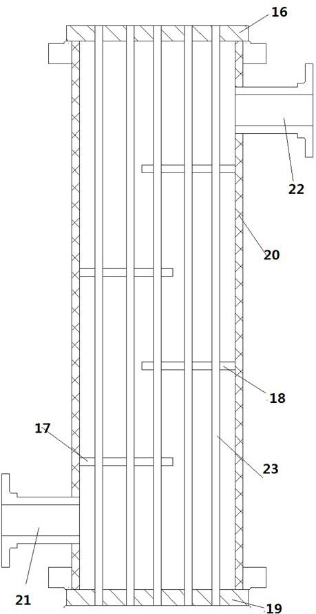
[0031] A shell-and-tube heat exchanger, such as figure 1 As shown, the shell-and-tube heat exchanger includes a shell 20, a heat exchange component 23, a shell-side inlet connection 21 and a shell-side outlet connection 22; the shell-side inlet connection 21 and the shell-side outlet connection 22 are respectively located in the The upper end and the lower end of the heat exchanger; the heat exchange component 23 is arranged in the shell 20, and the heat exchange component is fixedly connected to the upper tube plate 16 and the lower tube plate 19; the shell side inlet connection 21 and the shell side outlet connection 22 are all arranged on the shell 20; the gas enters from the shell-side inlet connecting pipe 21, passes through the heat exchange components for heat exchange, and exits through the shell-side outlet connecting pipe 22.

[0032] Preferably, the heat exchange component extends along the vertical direction. The heat exchangers are arranged vertically.

[0033] ...


PUM


Abstract

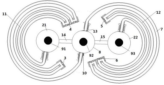
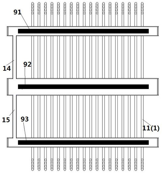
The invention provides a loop heat tube heat exchanger capable of switching heat sources to heat gas. A first liquid level sensor, a second liquid level sensor and a third liquid level sensor are correspondingly arranged in a left side tube, a central tube and a right side tube and are used for detecting liquid levels in the left side tube, the right side tube and the central tube; and the first liquid level sensor, the second liquid level sensor and the third liquid level sensor are in data connection with a controller, the controller extracts liquid level data of a left tube box, a right tube box and a middle tube box according to the time sequence, the liquid level data of adjacent time periods are compared to obtain the liquid level difference or accumulation of liquid level difference changes, and when the liquid level data are lower than a threshold value, the controller controls whether a first heat source, a third heat source and a second heat source conduct heating or not. According to the rotationally symmetrical gas heat exchange shell-and-tube heat exchanger, a new heat source is started to perform alternate heat exchange by detecting the liquid level difference change in the left side tube, the right side tube and the central tube, so that the heat exchange effect and the descaling effect are improved.

Description


Claims


Application Information

Patent Timeline
Owner SHANDONG UNIV
Why Eureka
Try Eureka