Nuclear power station radioactive liquid effluent discharging and conveying method

A radioactive and effluent technology, applied in the field of nuclear power, can solve the problems of high initial investment, interference, and failure to monitor and timely repair the damage of external protective trenches, and achieve the effect of reducing initial investment and reducing environmental risks

Pending Publication Date: 2021-07-20
中广核工程有限公司 +3
17 Cites 0 Cited by

AI-Extracted Technical Summary

Problems solved by technology

[0004] However, the prior art has at least the following defects: the initial investment is relatively high; the damage of the external protective pipe trench cannot be monitored and repai...

Method used

[0037] 1) By laying the radioactive liquid effluent discharge pipeline into the non-radioactive liquid effluent discharge pipeline, the initial investment is effectively reduced.
[0038] 2) In principle, the leakage of the radioactive liquid effluent is changed from outward leakage to inward leakage, thereby re...

Abstract

The invention discloses a nuclear power station radioactive liquid effluent discharging and conveying method. The method comprises the following steps that a non-radioactive liquid effluent discharging pipeline is laid; the radioactive liquid effluent discharge pipeline is laid in the non-radioactive effluent discharge pipeline, and the radioactive liquid effluent discharge pipeline is laid at the inner bottom of the non-radioactive liquid effluent discharge pipeline; when the non-radioactive liquid effluent discharge pipeline discharges, the radioactive liquid effluent discharge pipeline is ensured to be submerged and bear a certain external pressure, and the water head of the radioactive liquid effluent discharge pipeline at any point is lower than the water head of the non-radioactive liquid effluent discharge pipeline. Compared with the prior art, the radioactive liquid effluent discharge pipeline is laid in the non-radioactive liquid effluent discharge pipeline, the initial investment is effectively reduced, leakage of the radioactive liquid effluent pipeline can be converted into inward leakage of the non-radioactive liquid effluent from outward leakage of the radioactive liquid effluent, and therefore, the environmental risk is reduced.

Application Domain

Nuclear energy generationNuclear monitoring +1

Technology Topic

Process engineeringNuclear power plant +2

Image

  • Nuclear power station radioactive liquid effluent discharging and conveying method

Examples

  • Experimental program(1)

Example Embodiment

[0025] In order to make the invention purpose, technical solutions and beneficial technical effects of the present invention clearer, the present invention will be further described in detail below with reference to the accompanying drawings and specific embodiments. It should be understood that the specific embodiments described in this specification are only for explaining the present invention, and not for limiting the present invention.
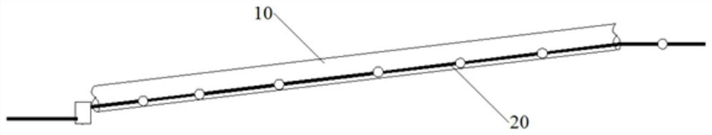
[0026] Please refer to figure 1 As shown, the nuclear power plant radioactive liquid effluent discharge and conveying method of the present invention comprises the following steps:
[0027] Lay non-radioactive liquid effluent discharge pipeline 10;
[0028] The radioactive liquid effluent discharge pipe 20 is laid in the non-radioactive liquid effluent discharge pipe 10, and the radioactive liquid effluent discharge pipe 20 is laid on the inner bottom of the non-radioactive liquid effluent discharge pipe 10; and
[0029] When the non-radioactive liquid effluent discharge pipeline 10 discharges, the radioactive liquid effluent discharge pipeline 20 is guaranteed to be submerged and has a certain external pressure, and the water head of the radioactive liquid effluent discharge pipeline 20 at any point is lower than that of the non-radioactive liquid effluent discharge Head of pipe 10.
[0030] According to an embodiment of the present invention, a pressurized pump station can be set up before the radioactive liquid effluent enters the water body, and the radioactive liquid effluent discharge gap in the pressurized pump station can be judged according to the change of the liquid level in the pool of the radioactive liquid effluent and the operation of the pump group. Whether the liquid effluent discharge pipeline 20 is leaking; according to an embodiment of the present invention, before the radioactive liquid effluent enters the water body, a pressurized pump station may not be set up, and the radioactive liquid effluent discharge pipeline 20 before entering the sea may not be provided with a pressurized pump station. A flow leakage monitoring device (such as a flow switch) is used to determine whether leakage occurs in the radioactive liquid effluent discharge pipeline 20 . The above two schemes can effectively reduce the work intensity of leak detection and the required investment.
[0031] According to an embodiment of the present invention, a flow detection device can be installed on the radioactive liquid effluent discharge pipeline 20 for automatic real-time monitoring, to determine the leakage of the pipeline and locate the position of the leaked section of the pipeline, so as to prepare for maintenance in advance.
[0032] According to an embodiment of the present invention, measures such as inspection ports, pipe sight glasses, flow switches, etc. are provided at intervals along the radioactive liquid effluent discharge pipeline 20, so as to inspect the radioactive liquid effluent discharge pipeline 20 in the undrained gap. Check whether there is water flow, to judge whether the radioactive liquid effluent discharge pipeline 20 leaks, or in the case of confirming the leak, judge the location of the leaked pipe section based on the water flow condition, so as to prepare for maintenance.
[0033] Specifically, radioactive liquid effluents are discharged intermittently all year round, while non-radioactive liquid effluents such as sewage from cooling towers of nuclear power plants are continuously discharged, which ensures that the discharge pipes of radioactive liquid effluents are subject to a certain external pressure. If a rupture occurs, the non-radioactive liquid effluent leaks into the radioactive liquid effluent discharge pipeline 20 due to external pressure, which can be determined by the water flow in the radioactive liquid effluent discharge pipeline and the liquid level change in the pump pit before entering the water body. As well as the start-up of the booster pump and the alarm of the flow switch at the outlet of the joint pipeline, to determine whether the radioactive liquid effluent discharge pipeline 20 is ruptured, so as to ensure that the failure of the radioactive liquid effluent discharge pipeline 20 can be detected in time, and the radioactive liquid effluent discharge pipeline 20 can be detected in time. Organizing repairs in the event that the drain stops draining. In addition, flow switches can also be provided in sections along the radioactive liquid effluent discharge pipeline 20, and the position of the pipeline damage can be determined by the action of the flow switch.
[0034] During the discharge, because the water head at any point of the radioactive liquid effluent discharge pipeline 20 is lower than the water head of the non-radioactive liquid effluent discharge pipeline 10, if the radioactive liquid effluent discharge pipeline 20 is damaged, the non-radioactive liquid effluent will enter the radioactive liquid effluent. In the effluent discharge pipeline 20, the radioactive liquid effluent will not be polluted due to external leakage.
[0035] Because the radioactive liquid effluent discharge pipe 20 is protected by the non-radioactive liquid discharge pipe 10, external mechanical damage can be effectively avoided. Due to the continuous operation of the non-radioactive liquid effluent discharge pipeline 10, if it is ruptured due to external construction, vehicle rolling, etc., it will be found and repaired due to water leakage. The liquid discharge of the non-radioactive liquid effluent discharge pipeline 10 can be monitored objectively. The function of the alarm ensures the effectiveness of the protection measures for the discharge pipeline of radioactive liquid effluent.
[0036] It can be seen from the above detailed description of the present invention that, compared with the prior art, the method for discharging and conveying radioactive liquid effluent from a nuclear power plant of the present invention has the following advantages:
[0037] 1) By placing the radioactive liquid effluent discharge pipeline into the non-radioactive liquid effluent discharge pipeline, the initial investment is effectively reduced.
[0038] 2) In principle, the leakage of radioactive liquid effluent is converted from outward leakage to inward leakage, thereby reducing the environmental risk.
[0039] 3) Real-time monitoring and localization of leakage of radioactive liquid effluent discharge pipelines can be realized.
[0040]4) Due to the characteristics of the radioactive liquid effluent discharge pipeline, the external non-radioactive liquid effluent discharge pipeline leaks water into the radioactive liquid effluent discharge pipeline when there is a small break in the pipeline. It is said that relevant work can be prepared in advance, and the pipeline can be overhauled during the shutdown of the nuclear power plant to avoid affecting the normal operation of the unit.
[0041] 5) The consequences of the destruction of the external non-radioactive liquid effluent discharge pipeline generally cause concern, thus ensuring that the protection facilities of the radioactive liquid effluent discharge pipeline can effectively protect the internal pipeline.
[0042] Based on the disclosure and teaching of the above specification, those skilled in the art to which the present invention pertains can also make appropriate changes and modifications to the above embodiments. Therefore, the present invention is not limited to the specific embodiments disclosed and described above, and some modifications and changes to the present invention should also fall within the protection scope of the claims of the present invention. In addition, although some specific terms are used in this specification, these terms are only for convenience of description and do not constitute any limitation to the present invention.

PUM

no PUM

Description & Claims & Application Information

We can also present the details of the Description, Claims and Application information to help users get a comprehensive understanding of the technical details of the patent, such as background art, summary of invention, brief description of drawings, description of embodiments, and other original content. On the other hand, users can also determine the specific scope of protection of the technology through the list of claims; as well as understand the changes in the life cycle of the technology with the presentation of the patent timeline. Login to view more.

Similar technology patents

Ice-storage refrigeration device and ice-storage refrigeration system

InactiveCN101532709Aless investmentLower initial investment
Owner:袁东立

Carbon nitride hollow sphere photocatalyst, preparation method and application thereof

InactiveCN106582761AThe synthesis process is simpleReduce environmental risks
Owner:JIANGSU UNIV OF SCI & TECH

High acid crude oil electric desalting wastewater treatment method

ActiveCN103102035AReduce environmental risksSmall footprint
Owner:CHINA PETROLEUM & CHEM CORP +1

Method for fixing chlorobenzene volatile organic pollutants by straw biomass charcoal

InactiveCN103056156AReduce environmental risksimproved soil
Owner:INST OF SOIL SCI CHINESE ACAD OF SCI

High-concentration organic wastewater resource utilization method

InactiveCN109576031AReduce environmental risksprevent leakage
Owner:南京馥安投资管理有限公司

Clean treatment technology for shale gas oil-based ash residues

InactiveCN109819869AReduce environmental risksUse properly
Owner:重庆市涪陵页岩气环保研发与技术服务中心

Classification and recommendation of technical efficacy words

  • Reduce environmental risks
  • Lower initial investment

Method for fixing chlorobenzene volatile organic pollutants by straw biomass charcoal

InactiveCN103056156AReduce environmental risksimproved soil
Owner:INST OF SOIL SCI CHINESE ACAD OF SCI

Carbon nitride hollow sphere photocatalyst, preparation method and application thereof

InactiveCN106582761AThe synthesis process is simpleReduce environmental risks
Owner:JIANGSU UNIV OF SCI & TECH

High acid crude oil electric desalting wastewater treatment method

ActiveCN103102035AReduce environmental risksSmall footprint
Owner:CHINA PETROLEUM & CHEM CORP +1

High-concentration organic wastewater resource utilization method

InactiveCN109576031AReduce environmental risksprevent leakage
Owner:南京馥安投资管理有限公司

Clean treatment technology for shale gas oil-based ash residues

InactiveCN109819869AReduce environmental risksUse properly
Owner:重庆市涪陵页岩气环保研发与技术服务中心

Ice-storage refrigeration device and ice-storage refrigeration system

InactiveCN101532709Aless investmentLower initial investment
Owner:袁东立
Why Eureka
Try Eureka