Low-temperature water cooling system

A cold water system and low-temperature technology, applied in refrigerators, refrigeration components, refrigeration and liquefaction, etc., can solve the problems of deteriorating compressor operating environment, small cooling capacity range, and lower exhaust temperature, so as to increase the cooling capacity range and improve Cooling capacity range, effect of lowering condensation temperature

Active Publication Date: 2014-01-01
烟台欧森纳地源空调股份有限公司 +1
View PDF10 Cites 0 Cited by
  • Summary
  • Abstract
  • Description
  • Claims
  • Application Information

AI Technical Summary

Problems solved by technology

This configuration makes the unit run at a lower evaporating temperature and a higher condensing temperature, and the cooling efficiency of the unit is greatly reduced
At the same time, when the compressor is running in this working condition, the exhaust temperature and oil temperature are high, which deteriorates the operating environment of the compressor.
For this reason, in the prior art, the refrigerant liquid is sprayed to the compressor to reduce the discharge temperature; the refrigerant liquid is injected to cool the temperature of the refrigerated oil, and the refrigerant enters the compressor again. Although this method can effectively reduce the temperature of the compressor The exhaust temperature and the temperature of the refrigerating oil, but the injected refrigerant and the refrigerant that cools the refrigerating oil enter the compressor for compression cycle, which reduces the refrigerant that should have evaporated and refrigerated in the evaporator, reduces the cooling capacity of the unit and increases The power consumption of the compressor reduces the cooling efficiency of the system; in addition, the operating environment of the low-temperature cold water system is different, and because the operating conditions of the system change greatly, it is necessary for the liquid supply system to have a wide adjustment range; and the current low-temperature cold water The system generally uses a single semi-hermetic screw compressor with a small range of cooling capacity

Method used


Image

  • Low-temperature water cooling system

Examples


Embodiment Construction

[0014] The principles and features of the present invention are described below in conjunction with the accompanying drawings, and the examples given are only used to explain the present invention, and are not intended to limit the scope of the present invention.

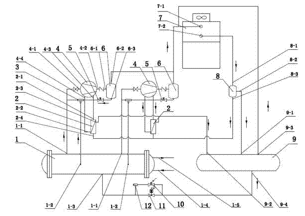
[0015] Such as figure 1 As shown, a low-temperature cold water system includes a low-temperature flooded evaporator 1, a liquid distributor 8, a liquid reservoir 9, and at least one screw compressor system, and the screw compressor system includes a plate oil-cooled heat exchanger 2 , injection pump 3, screw compressor 4, first electromagnetic valve 5 and oil separator 6, it is characterized in that, described low-temperature cold water system also comprises evaporative condenser 7, and the compressor intake of described screw compressor 4 Port 4-1 is connected to the evaporator gas outlet 1-1 of the low-temperature flooded evaporator 1, and the compressor exhaust port 4-2 of the screw compressor is connected to the...


PUM


Abstract

The invention relates to a low-temperature water cooling system which comprises a low-temperature flooded evaporator, a liquid distributor, a liquid storer and at least one set of screw compressor system. Each screw compressor system comprises a plate-type oil cooling heat exchanger, a jet pump, a screw compressor, a first electromagnetic valve and an oil separator. The low-temperature water cooling system is characterized by further comprising an evaporation-type condenser, and a liquid bypass liquid-supply system and two sets of the screw compressor systems are further arranged between the low-temperature flooded evaporator and the liquid storer. The low-temperature water cooling system has the advantages that cooling capacity of the low-temperature water cooling system is improved, operating conditions of the compressors are effectively improved, operating conditions of the whole system are improved, and refrigerating efficiency of the whole refrigerating system is improved.

Description

technical field [0001] The invention relates to the technical field of refrigeration, in particular to a low-temperature cold water system. Background technique [0002] At present, in the existing low-temperature cold water system, the evaporator mostly adopts a dry evaporator, and the condenser adopts a water-cooled condenser. The water-cooled condenser needs to be equipped with a cooling tower, a cooling water pump and a cooling water system, and the initial investment is relatively high. This configuration makes the unit run at a lower evaporation temperature and a higher condensation temperature, and the cooling efficiency of the unit is greatly reduced. At the same time, when the compressor is running in this working condition, the exhaust temperature and oil temperature are high, which deteriorates the operating environment of the compressor. For this reason, in the prior art, the refrigerant liquid is sprayed to the compressor to reduce the discharge temperature; th...

Claims


Application Information

Patent Timeline
IPC IPC(8): F25B1/047F25B1/10F25B39/02F25B41/00F25B41/40
Inventor 高一峰崔魁许琨姜民智
Owner 烟台欧森纳地源空调股份有限公司
Why Eureka
Try Eureka