Communication equipment for power system

A technology of communication equipment and power system, applied in the direction of electrical equipment shell/cabinet/drawer, electrical components, folding antenna, etc., can solve the problems of inconvenient moving position, fixed installation position, inconvenient use, etc., to achieve convenient moving position, improve air The effect of the flow effect

Active Publication Date: 2021-07-20
TIANJIN UNIV +1
View PDF5 Cites 0 Cited by
  • Summary
  • Abstract
  • Description
  • Claims
  • Application Information

AI Technical Summary

Problems solved by technology

[0004] The invention provides a communication device for a power system to solve the problem that the installation position of the current communication device for a power system is relatively fixed, which leads to too inconvenient moving position and inconvenient use

Method used


Image

  • Communication equipment for power system
  • Communication equipment for power system
  • Communication equipment for power system

Examples


Embodiment Construction

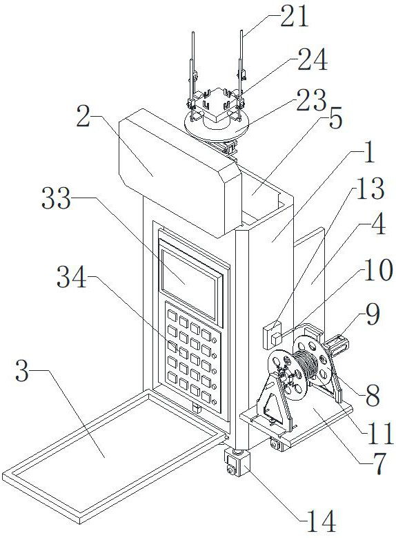
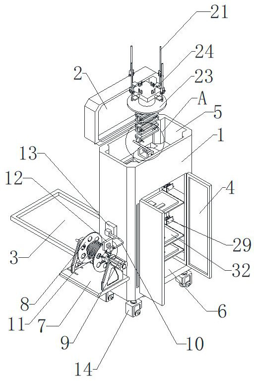
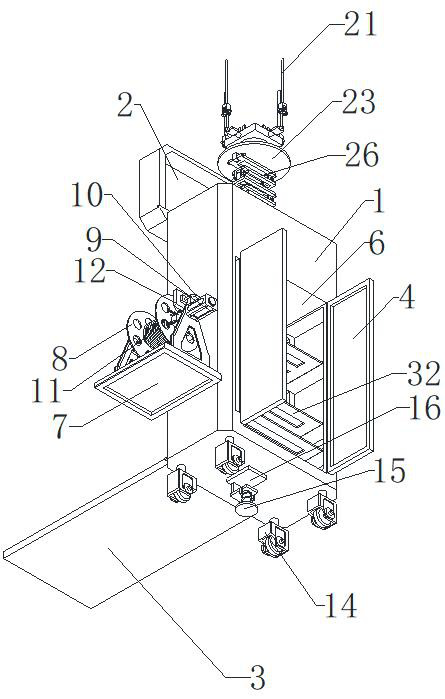
[0032] see Figure 1 to Figure 8 :

[0033] The present invention provides a communication device for a power system, including a metal cabinet 1. The components of a communication device for a power system are described in detail below:

[0034] The upper end of the metal cabinet 1 is provided with a receiving groove 5, and the inner bottom of the receiving groove 5 is provided with several folded pieces 26 distributed up and down, and two adjacent folded pieces 26 are threadedly connected with two bolts 27. A support plate 23 is arranged above the uppermost folded piece 26, the lower end of the support plate 23 is threadedly connected with the head end of the uppermost folded piece 26 with a bolt 222, and the tail end of the lowermost folded piece 26 is connected to the receiving end. Bolt three 28 are threadedly connected between the inner bottom ends of the groove 5;

[0035] The outside of the support plate 23 is provided with several antennas 21 distributed in a ring s...


PUM


Abstract

The invention relates to the technical field of communication equipment, in particular to communication equipment for an electric power system, which comprises a metal cabinet, a storage groove is formed in the upper end of the metal cabinet, a plurality of folding pieces distributed up and down are arranged at the bottom end in the storage groove, a second bolt is in threaded connection between every two adjacent folding pieces, and a supporting disc is arranged above the folding piece at the uppermost end. A fourth bolt is in threaded connection with the lower end of the supporting disc and the head end of the folding piece at the uppermost end, a third bolt is in threaded connection between the tail end of the folding piece at the lowermost end and the inner bottom end of the containing groove, and the fourth bolt, the second bolt and the third bolt are rotated to enable the folding pieces to stretch and contract so that the supporting disc can ascend and descend. The extension folding part can adjust the placing height of the antenna, the motor drives the wire wheel to rotate so that the cable can be wound and unwound, universal wheels can conveniently move the position of the metal cabinet, and the problems that the installation position of existing communication equipment for the electric power system is fixed, the position moving is too inconvenient, and use is inconvenient are solved.

Description

technical field [0001] The invention relates to the technical field of communication equipment, in particular to a communication equipment used in a power system. Background technique [0002] The power system is a power facility composed of power plants, power transmission and transformation lines, power supply and distribution stations, and power consumption. The system maintains normal operation, wired communication equipment and wireless communication equipment for industrial control environment. Often during the operation of the power system, due to the need to control the power system, it is necessary to establish a communication bridge between the power system and the staff to maintain the necessary communication between people and the system, and communication equipment has become a human The connection link for communication with the system, so the application of communication equipment was born. [0003] The current communication equipment is used in relatively f...

Claims


Application Information

Patent Timeline
Patent Type & Authority Applications(China)
IPC IPC(8): H05K5/02H05K7/14H01Q1/08
CPCH01Q1/08H05K5/0217H05K7/14
Inventor 秦培均车延博苏才军杨建雄尹小惠
Owner TIANJIN UNIV
Why Eureka
Try Eureka