Injection device for injection molding machine and injection molding system thereof

An injection molding machine and injection device technology, applied in the field of injection molding machines, can solve the problems of downtime, inconvenient use, and inability to produce normally, and achieve the effect of timely cleaning

Inactive Publication Date: 2021-07-23
柏松
View PDF1 Cites 0 Cited by
  • Summary
  • Abstract
  • Description
  • Claims
  • Application Information

AI Technical Summary

Problems solved by technology

[0004] However, there are still obvious defects in its use: 1. After the injection of the above device is completed, molten raw materials will continue to flow out of the nozzle, which will seriously affect the aesthetics of injection molding products and reduce product quality; 2. 1. Recycling materials and some stabilizers, fillers and other additives are often added to plastic raw materials. Due to the different melting points of plastic raw materials and additives, the molten colloid in the material tube cannot be fully melted under different working conditions, and there will be large Granular solid substances, when these solid substances flow through the small nozzle holes, they are easy to block the nozzle holes and lead to abnormal production. Therefore, the above-mentioned devices need to be shut down frequently during use, which is inconvenient to use and low in processing efficiency.

Method used


Image

  • Injection device for injection molding machine and injection molding system thereof
  • Injection device for injection molding machine and injection molding system thereof
  • Injection device for injection molding machine and injection molding system thereof

Examples


Embodiment 1

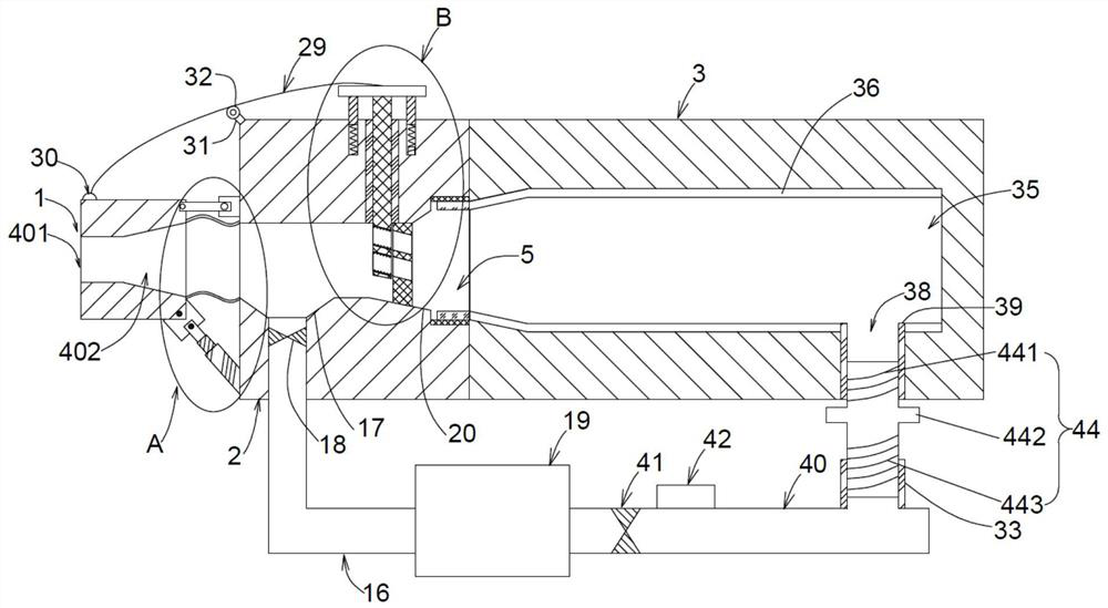
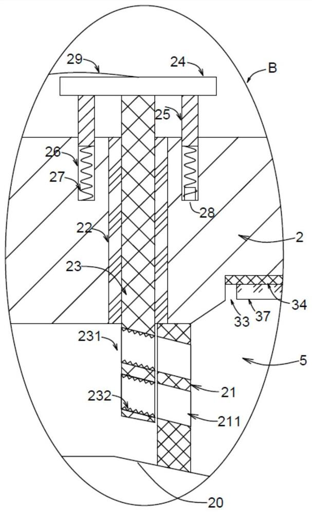
[0044] Embodiment 1: When spraying molten liquid plastic, open the feed pipe valve 41 and the feed pump 42, so that the liquid plastic in the material storage tank 19 will enter through the inner chamber of the feed pipe 40 and the feed connector 44 In the feeding cavity 35, spraying is performed after passing through the guide cavity 5, the tapered channel 402 and the straight channel 401 in sequence, and the liquid plastic is introduced into the mould.

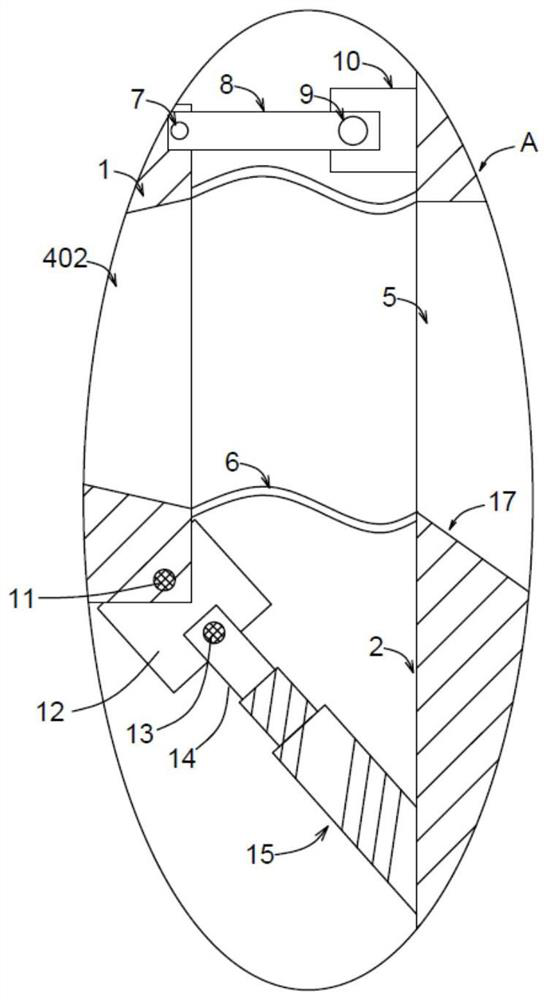
[0045] After the injection is finished, the cylinder 15 starts immediately, and the extension of the cylinder 15 drives the outlet end of the injection head 1 to tilt upward, so that the excess liquid plastic in the straight channel 401 and the tapered channel 402 returns in time, and the returned liquid plastic collects in the collection tank 17 In the process, the flow is blocked in time to avoid the phenomenon of wire drawing and flow, which will pollute the injection molded products.

[0046] It should be noted that when...

Embodiment 2

[0048] Embodiment 2: After using for a long period of time, more solid particle impurities may have accumulated in the gap of the groove 33. At this time, the middle section 442 of the material guide connector 44 is held by hand and rotated downward, so that the material guide The lower hollow threaded rod 443 of the connector 44 is more screwed into the lower threaded ring 43 until the upper hollow threaded rod 441 breaks away from the upper threaded ring 39; 37 breaks away from the thread 34 in the groove 33, and then the groove 33 is exposed, which is convenient for centralized cleaning of the solid particle debris accumulated here, thereby effectively reducing the frequency of manual cleaning, making it more convenient to use and higher in processing efficiency.


PUM


Abstract

The invention provides an injection device for an injection molding machine and an injection molding system thereof. The injection device comprises an injection head, an injection seat and an injection connecting pipe, wherein an air cylinder is fixed on one side, close to the injection head, of the injection seat; a backflow pipe is arranged at the bottom of a flow guide cavity in a communicating mode; a plurality of filter screen holes are formed in a filter screen plate, a plurality of cutting teeth are fixedly arranged on the inner wall of a through hole, and a heavy plate is fixedly arranged at one end, far away from the flow guide cavity, of a cutting plate; and a feeding cavity is formed in the injection connecting pipe, and a material guide connecting piece is detachably connected between an upper threaded ring and a lower threaded ring. According to the injection device for the injection molding machine and the injection molding system thereof, molten plastic can be prevented from continuously flowing out in time after injection is completed, so that the molten plastic is prevented from polluting products; and a filtering device is arranged in the injection device, so that large-particle solid substances can be prevented from blocking the injection head, the intercepted large-particle solid substances can be automatically cut off, and the injection smoothness is ensured.

Description

technical field [0001] The invention relates to the technical field of injection molding machines, in particular to an injection device for an injection molding machine and an injection molding system thereof. Background technique [0002] Injection molding machine is a main molding equipment that uses plastic molding molds to make thermoplastic or thermosetting plastics into plastic products of various shapes. When it works, it needs to melt the solid raw material, and then inject it into the mold through the feeding tube and nozzle. In the current commonly used injection molding equipment, generally after the injection is completed, the molten raw material will continue to flow out of the nozzle, especially when the viscosity of the raw material is relatively low, the phenomenon is more serious. If the outflowing raw materials adhere to the formed product, the surface of the product will be uneven and unsightly, and it is easy to get defective products. In order to solve...

Claims


Application Information

Patent Timeline
IPC IPC(8): B29C45/20
CPCB29C45/20
Inventor 柏松
Owner 柏松
Why Eureka
Try Eureka