
Mold clamping mechanism and mold clamping rear seat plate of injection molding machine

A technology of mold clamping and back seat, applied in the field of mold clamping mechanism of injection molding machines, can solve the problems of cracking and deformation of the locking plate, unable to continue to use, and high weight of the locking plate, so as to enhance the performance of castings, reduce the probability of fatigue cracking, and optimize the weight.

Active Publication Date: 2022-02-01
BORCH MACHINERY
View PDF0 Cites 0 Cited by
  • Summary
  • Abstract
  • Description
  • Claims
  • Application Information

AI Technical Summary

Problems solved by technology

[0003] Most of the existing injection molding machines are clamped with tie rods. High-pressure oil is used to push the clamping piston to lock the pull rod of the injection molding machine. The inner ring gear in the clamping piston meshes with the locking ring gear on the pull rod to complete the mold clamping. process, but the stress concentration of the existing clamping mechanism during the clamping process causes the clamping plate to crack and deform after a period of use, making it impossible to continue to use, and the clamping plate has the disadvantages of high weight and insufficient rigidity

Method used


Image

  • Mold clamping mechanism and mold clamping rear seat plate of injection molding machine
  • Mold clamping mechanism and mold clamping rear seat plate of injection molding machine
  • Mold clamping mechanism and mold clamping rear seat plate of injection molding machine

Examples


Embodiment Construction

[0022] The technical solutions of the present invention will be clearly and completely described below in conjunction with the embodiments. Apparently, the described embodiments are only some of the embodiments of the present invention, not all of them. Based on the embodiments of the present invention, all other embodiments obtained by persons of ordinary skill in the art without creative efforts fall within the protection scope of the present invention.

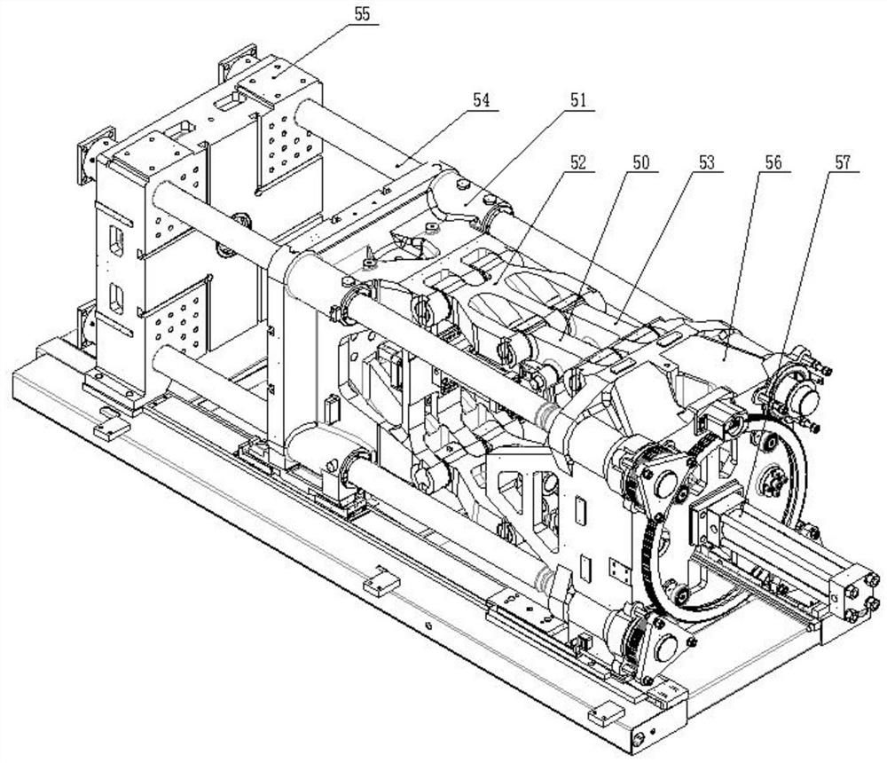
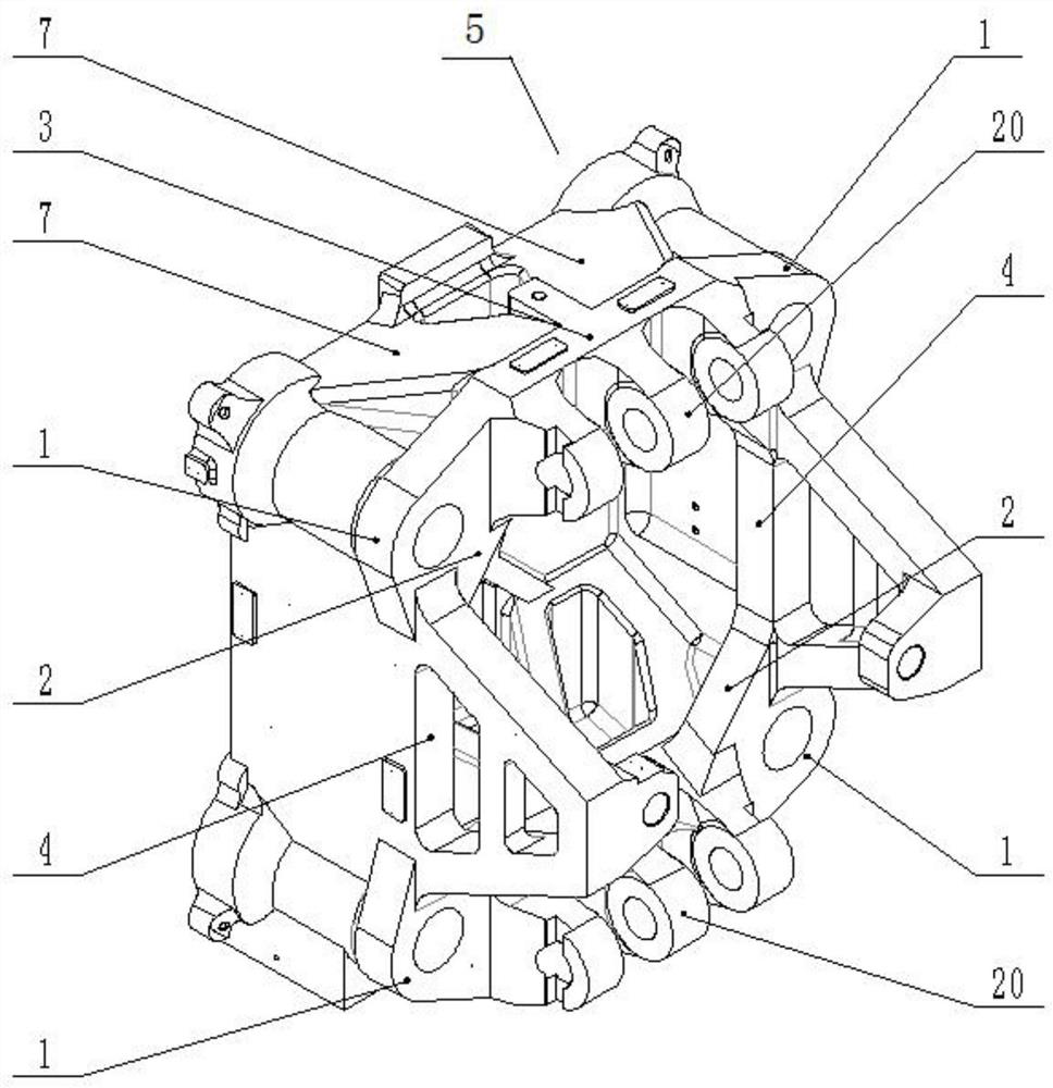
[0023] see Figure 1-5 As shown, a mold clamping mechanism of an injection molding machine includes a mold clamping plate 55 and a mold clamping tail plate 56, and a mold clamping moving plate 51 is arranged between the mold clamping plate 55 and the mold locking tail plate 56; The four corners of the plate 55 are fixedly equipped with pull rods 54, the other end of the pull rod 54 is fixedly mounted on the mold clamping tail plate 56, the mold clamping movable plate 51 is slidably installed on the pull rod 54, and the mold...


PUM


Abstract

The invention discloses a mold locking mechanism and a mold locking rear seat plate of an injection molding machine, comprising a mold locking plate and a mold locking tail plate, a mold locking moving plate is arranged between the mold locking plate and the mold locking tail plate; the lock Tie rods are fixedly installed at the four corners of the mold locking plate, the other end of the tie rod is fixedly installed on the mold locking tail plate, the mold locking moving plate is slidably installed on the tie rod, and the side of the mold locking moving plate close to the locking mold tail plate rotates Two sets of long hinges are installed, and the two sets of long hinges are symmetrically distributed up and down on the clamping movable plate. The mold clamping tail plate is fixedly installed in the center of the side away from the clamping movable plate, and the output of the clamping cylinder is fixed. The end is fixedly connected with the mold clamping moving plate. Through the new structural layout, the invention can reduce the stress concentration problem caused by the deformation of the tail plate during the mold clamping process, reduce the fatigue cracking probability of the tail plate after many years of use, reduce the structural deformation of the mold clamping tail plate, and increase the The rigidity of the clamping mechanism can optimize the weight of the parts and reduce the cost at the same time.

Description

technical field [0001] The invention belongs to the technical field of mold clamping mechanisms of injection molding machines, and in particular relates to a mold clamping mechanism of injection molding machines and a mold clamping rear seat plate. Background technique [0002] Generally, injection molding machines on the market are the main molding equipment for making thermoplastic materials or thermosetting materials into various shapes of plastic products with plastic molding molds. Therefore, the role of molds in injection molding machines is relatively important. According to different shapes of plastic products Manufacture the corresponding mold for production, with high efficiency and good quality; generally, the mold of the injection molding machine includes a movable template and a fixed template, and the production of the product is realized through the cooperation of the movable template and the fixed template, because the injection molding machine is in the injec...

Claims


Application Information

Patent Timeline
Patent Type & Authority Patents(China)
IPC IPC(8): B29C45/67
CPCB29C45/67
Inventor 吴小廷孙晓波袁中华杜呈表周清华刘媛
Owner BORCH MACHINERY
Learn More