Unmanned aerial vehicle group launching mechanism
A technology of unmanned aerial vehicle and launching mechanism, which is applied in the direction of launch/tow transmission device, etc., can solve the problems of low launch efficiency and speed, large impact damage of UAV, and high launch cost, achieve automatic launch, avoid motion interference, improve The effect of emission efficiency
- Summary
- Abstract
- Description
- Claims
- Application Information
AI Technical Summary
Problems solved by technology
Method used
Image
Examples
specific Embodiment approach 1
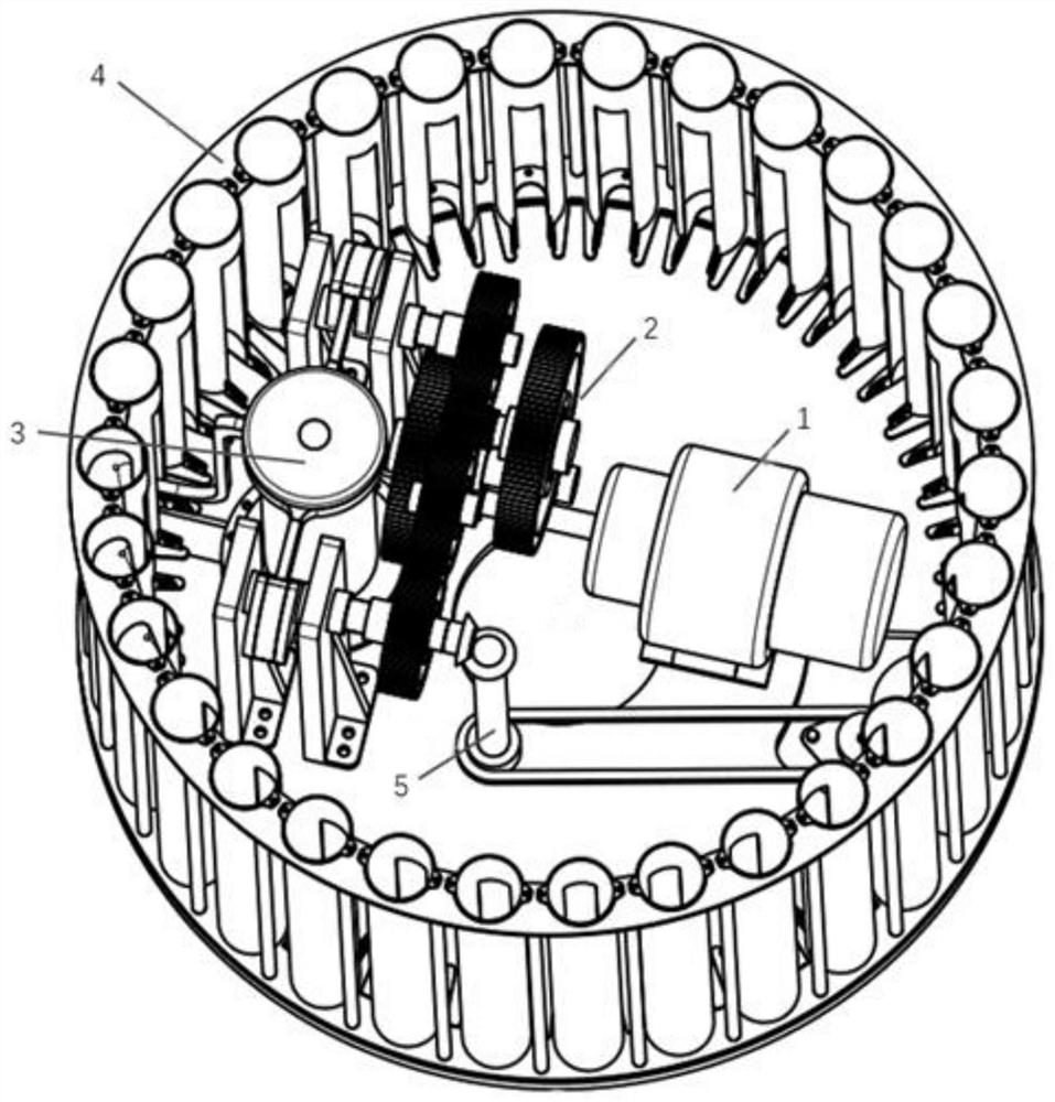
[0050] Specific implementation mode one: please refer to Figure 1-20 , the present invention provides a technical solution: an unmanned aerial vehicle group sending mechanism, comprising:
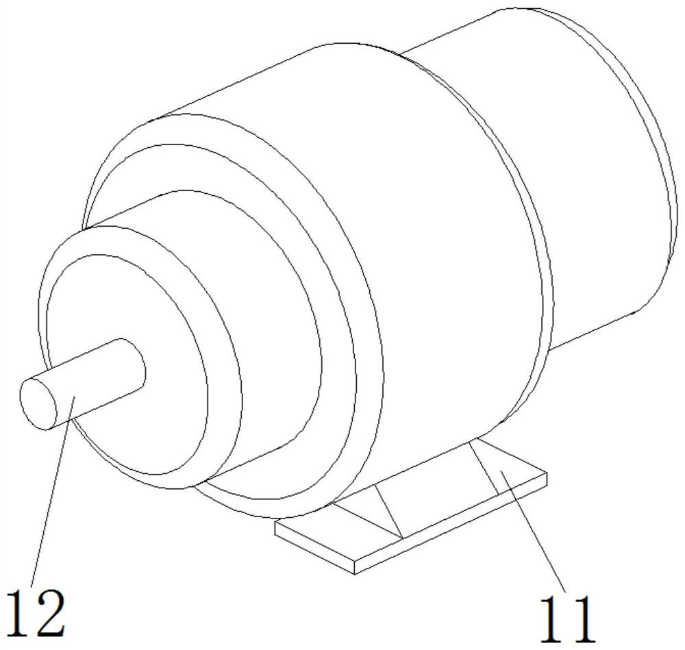
[0051] The motor 1, as a power source, provides power for the operation of the mechanism, and the motor output shaft 12 of the motor 1 is connected to the reduction system 2;
[0052] The deceleration system 2 is used to decelerate the input power and increase the torque and drive the launch mechanism 3 to work. The deceleration system 2 is connected to the transmission assembly 5 through the first bevel gear 262;
[0053] The launch mechanism 3 is used to launch the unmanned aerial vehicle;
[0054] The delivery mechanism 4 is used to transport the unmanned aerial vehicle into the launch mechanism 3;
[0055] The transmission assembly 5 is used to transmit the power to the conveying mechanism 4;
[0056] The motor 1 , the launching mechanism 3 and the transmission assembly 5 are all in...
specific Embodiment approach 2
[0059] Specific embodiment two: this embodiment is a further limitation of specific embodiment one, such as figure 1 and figure 2 As shown, the motor bottom plate 11 of the motor 1 is screwed and fixed together with the carrier plate 41, the motor output shaft 12 of the motor 1 is connected to the first-stage gear shaft 21 through a coupling 211, and the motor 1 provides the launching mechanism 3 and the conveying mechanism 4 with power.
specific Embodiment approach 3
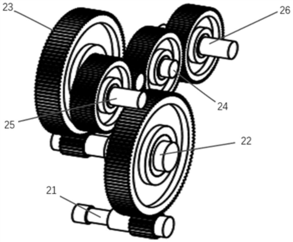
[0060] Specific implementation mode three: this implementation mode is a further limitation of specific implementation mode one, such as Figure 3-6 As shown, the reduction system 2 includes a first-stage gear shaft 21, a second-stage gear shaft 22, a third-stage gear shaft 23, a direction gear shaft 24, an output gear shaft I 25 and an output gear shaft II 26, and the first-stage gear shaft 21 A shaft coupling 211 is installed at the input end, a pinion is arranged at the output end of the first stage gear shaft 21, a large gear and a pinion are respectively fixed at both ends of the second stage gear shaft 22, and a large gear and a pinion are respectively fixed at both ends of the third stage gear shaft 23. A large gear and a pinion are respectively fixed, the pinion of the first stage gear shaft 21 meshes with the large gear of the second stage gear shaft 22, the small gear of the second stage gear shaft 22 meshes with the large gear of the third stage gear shaft 23 The pi...
PUM
 Abstract
Description
Claims
Application Information
 - R&D
- Intellectual Property
- Life Sciences
- Materials
- Tech Scout
- Unparalleled Data Quality
- Higher Quality Content
- 60% Fewer Hallucinations
Browse by: Latest US Patents, China's latest patents, Technical Efficacy Thesaurus, Application Domain, Technology Topic, Popular Technical Reports.
© 2025 PatSnap. All rights reserved.Legal|Privacy policy|Modern Slavery Act Transparency Statement|Sitemap|About US| Contact US: help@patsnap.com


