Supercharge Your Innovation With Domain-Expert AI Agents!

Buoyancy acting device

A technology of doing work and buoyancy, applied in hydroelectric power generation, engine components, machines/engines, etc., can solve problems such as not being the best energy source

Pending Publication Date: 2021-07-23
李登谷 +1
View PDF0 Cites 0 Cited by
  • Summary
  • Abstract
  • Description
  • Claims
  • Application Information

AI Technical Summary

Problems solved by technology

[0003] Although the above natural energy can be utilized, it cannot be the best energy source for human beings

Method used


Image

  • Buoyancy acting device

Examples


Embodiment Construction

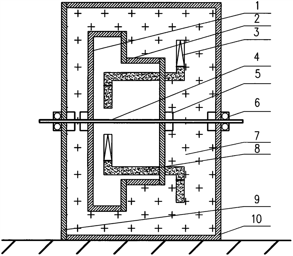
[0010] The present invention is described in detail below with reference to accompanying drawing: a kind of buoyancy acting device, it is characterized in that: liquid circulation pipe (8) two ends are equipped with sealing telescopic capsule (3), liquid circulation pipe (8) and sealing telescopic capsule (3) There is an appropriate amount of liquid, and the two ends of the rotating drum (2) are equipped with rotating drum sealing covers (1) to form a closed space for the rotating drum (2), and multiple sets of liquid circulation pipes (8) equipped with sealed telescopic capsules (3) are evenly installed on the The inner wall of the rotating drum (2), one end of the liquid circulation pipe (8) and the sealed telescopic capsule (3) are in the closed space of the rotating drum (2), and the other end and the sealed telescopic capsule (3) are in the closed space of the rotating drum (2). In the tank (10) liquid (7), the rotating drum (2) has a power output shaft (4), and the power ...


PUM


Abstract

The invention provides a buoyancy acting device. Sealing telescopic capsules are installed at the two ends of liquid flowing pipes, the liquid flowing pipes and the sealing telescopic capsules are each filled with a proper amount of liquid, rotating roller sealing covers are installed at the two ends of a rotating roller to form a rotating roller closed space, and the rotating roller closed space is immersed in liquid in a liquid box. The liquid flowing pipes are evenly installed on the inner wall of the rotating roller, one end of each liquid flowing pipe and the corresponding sealing telescopic capsule are arranged in the rotating roller closed space, and the other end of each liquid flowing pipe and the corresponding sealing telescopic capsule are arranged in the liquid of the liquid box outside the rotating roller closed space. The rotating roller is provided with a power output shaft, and the rotating roller, the rotating roller sealing covers and a shaft seal are immersed in the liquid of the liquid box. The mass of the liquid in the sealing telescopic capsules in the rotating roller closed space and the mass of the liquid in the sealing telescopic capsules in the liquid in the liquid box are mutually balanced, the gravity buoyancy new energy which only does positive work and does not do negative work is realized by utilizing the characteristics that the gravity is downward and the buoyancy is upward, and a great contribution is made to human beings.

Description

technical field [0001] The invention relates to a buoyancy work device, which belongs to the field of new energy. Background technique [0002] Existing natural energy includes water energy, wind energy, solar energy, geothermal energy, biomass energy, tidal energy, etc. They are all natural energy sources in nature. If they want to use these energy sources, their structures are complicated, their manufacturing costs are high, their maintenance costs are high, their ecological environment is seriously damaged, and there are major safety hazards. For example: wind energy requires a huge investment and cannot work normally for many hours a year; water energy requires a huge investment and requires construction of dams and diversion channels, many supporting projects, and the most important thing is to destroy the ecological environment, accompanied by major safety hazards, etc.; Solar energy, high production cost, low conversion efficiency of solar photovoltaic effect, large ...

Claims


Application Information

Patent Timeline
Patent Type & Authority Applications(China)
IPC IPC(8): F03B17/02
CPCF03B17/02Y02E10/20
Inventor 李登谷龚福清
Owner 李登谷
Features
  • R&D
  • Intellectual Property
  • Life Sciences
  • Materials
  • Tech Scout
  • Unparalleled Data Quality
  • Higher Quality Content
  • 60% Fewer Hallucinations
Learn More