Piston mechanism and hydraulic shock absorber

A piston mechanism and piston rod technology, applied in the direction of shock absorbers, shock absorbers, springs/shock absorbers, etc., can solve the difficulty of increasing the space layout of the vehicle chassis suspension, the large diameter of the shock absorber oil storage cylinder, and the increase in product weight And other issues

Pending Publication Date: 2021-07-23
FAWER AUTOMOTIVE PARTS +1
View PDF0 Cites 2 Cited by
  • Summary
  • Abstract
  • Description
  • Claims
  • Application Information

AI Technical Summary

Problems solved by technology

[0002] Hydraulic shock absorbers are commonly used in automobile suspension systems. During the working process of the shock absorber, the piston rod will reciprocate in the working cylinder of the shock absorber, and the oil in the oil storage cylinder will generate damping force through the valve system; the conventional electromagnetic The damping force of the valve is fixed, and the damping force of the shock absorber cannot be automatically controlled, so the electronically controlled shock absorber came into being
[0003] At present, the main electronically controlled shock absorbers are electronically controlled shock absorbers with external solenoid valves. The solenoid valves are placed outside the shock absorbers. By controlling the size of the oil circuit in the bypass passage, the control of the damping force is realized; The diameter of the oil storage cylinder is designed to be large, which is not conducive to the layout of the chassis. At the same time, the layout of the external solenoid valve also increases the difficulty of the space layout of the chassis suspension of the vehicle, and the external solenoid valve also increases the weight of the product, which virtually increases the weight of the vehicle.

Method used

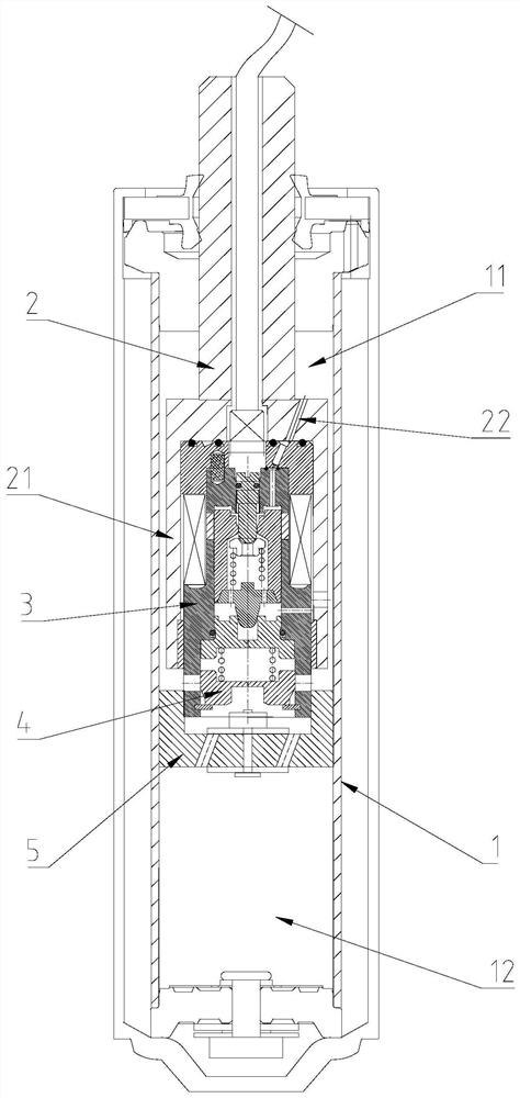
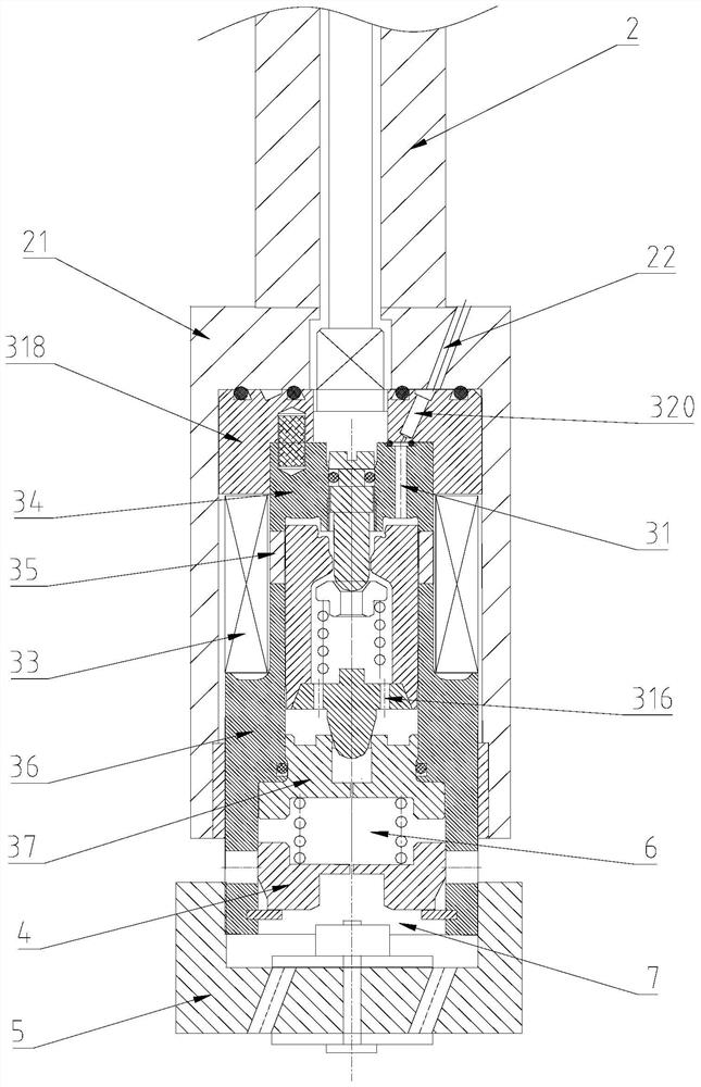
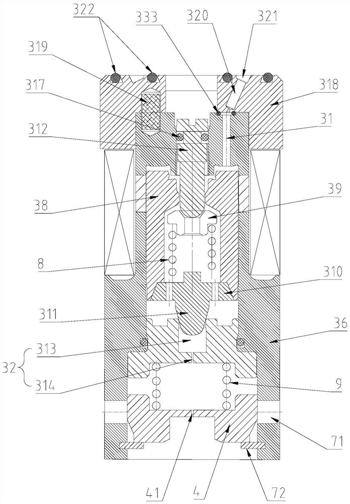

Image

  • Piston mechanism and hydraulic shock absorber
  • Piston mechanism and hydraulic shock absorber
  • Piston mechanism and hydraulic shock absorber

Examples


Embodiment Construction

[0029] The technical solutions of the present invention will be clearly and completely described below in conjunction with the accompanying drawings. Apparently, the described embodiments are some of the embodiments of the present invention, but not all of them.

[0030] The components of the embodiments of the invention generally described and shown in the figures herein may be arranged and designed in a variety of different configurations. Accordingly, the following detailed description of the embodiments of the invention provided in the accompanying drawings is not intended to limit the scope of the claimed invention, but merely represents selected embodiments of the invention.

[0031] Based on the embodiments of the present invention, all other embodiments obtained by persons of ordinary skill in the art without making creative efforts belong to the protection scope of the present invention.

[0032] In the description of the present invention, it should be noted that the...


PUM


Abstract

The invention relates to the technical field of shock absorbers, in particular to a piston mechanism and a hydraulic shock absorber. The piston mechanism comprises a piston rod, an electromagnetic valve assembly, a sliding valve and a rebuilt valve system, the piston rod is inserted into a working cylinder of the hydraulic shock absorber, the two ends of the electromagnetic valve assembly are connected with the piston rod and the rebuilt valve system respectively, the rebuilt valve system divides the working cylinder into a rod cavity and a rodless cavity, the sliding valve is located in a containing cavity formed by the rebuilt valve system and the electromagnetic valve assembly and divides the containing cavity into a first cavity and a second cavity, when the electromagnetic valve assembly is electrified, a first valve port and a second valve port of the electromagnetic valve assembly communicate, so that the first cavity communicates with the rod cavity through the electromagnetic valve assembly, a second through hole used for communicating the second cavity with the rod cavity is formed in the side wall of the second cavity, and the slide valve can shield the second through hole. The pressure of the first cavity is adjusted by adjusting the opening degree of the electromagnetic valve assembly so that the opening degree of the sliding valve can be adjusted, and then the damping force generated when oil passes through the rebuilt valve system can be adjusted.

Description

technical field [0001] The present application relates to the technical field of shock absorbers, in particular to a piston mechanism and a hydraulic shock absorber. Background technique [0002] Hydraulic shock absorbers are commonly used in automobile suspension systems. During the working process of the shock absorber, the piston rod will reciprocate in the working cylinder of the shock absorber, and the oil in the oil storage cylinder will generate damping force through the valve system; the conventional electromagnetic The damping force of the valve is fixed, and the damping force of the shock absorber cannot be automatically controlled, so the electronically controlled shock absorber came into being. [0003] At present, the main electronically controlled shock absorbers are electronically controlled shock absorbers with external solenoid valves. The solenoid valves are placed outside the shock absorbers, and the control of the damping force is realized by controlling ...

Claims


Application Information

Patent Timeline
Patent Type & Authority Applications(China)
IPC IPC(8): F16F9/34F16F9/36F16F9/46
CPCF16F9/34F16F9/369F16F9/464
Inventor 于洋
Owner FAWER AUTOMOTIVE PARTS
Why Eureka
Try Eureka