Bionic phase change energy storage steam cavity module

A technology of steam chamber and bionic phase, applied in lighting and heating equipment, indirect heat exchangers, etc., can solve the problems of low heat storage and heat release rate, uneven heat transfer during heat storage, and low thermal conductivity

Active Publication Date: 2021-07-23
XI AN JIAOTONG UNIV
View PDF14 Cites 2 Cited by
  • Summary
  • Abstract
  • Description
  • Claims
  • Application Information

AI Technical Summary

Problems solved by technology

[0013] This invention aims at the problems of low thermal conductivity of phase change materials in existing latent heat storage systems, uneven heat transfer during heat storag...

Method used


Image

  • Bionic phase change energy storage steam cavity module
  • Bionic phase change energy storage steam cavity module
  • Bionic phase change energy storage steam cavity module

Examples


Embodiment Construction

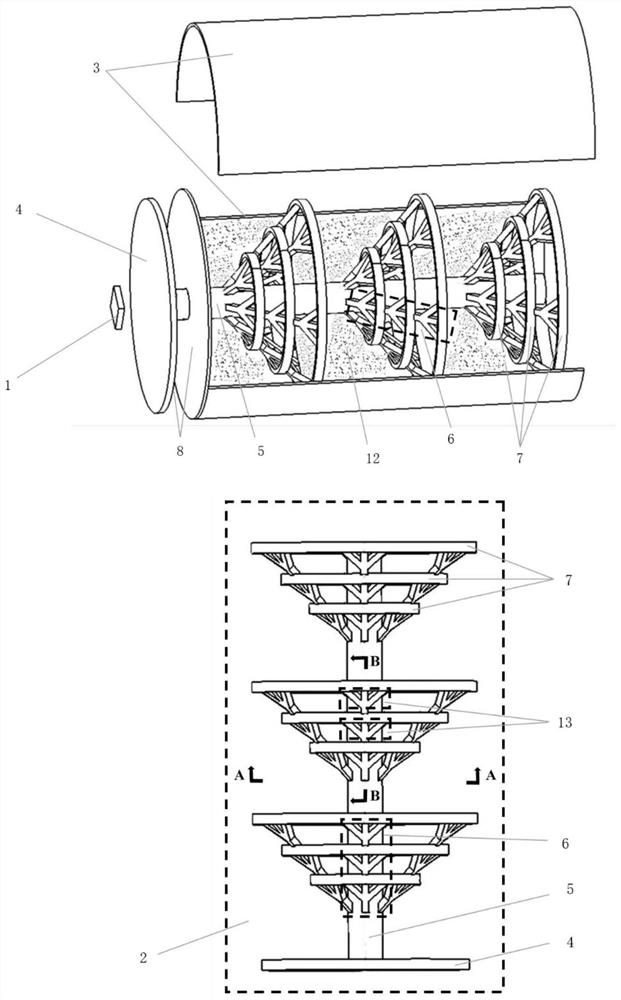
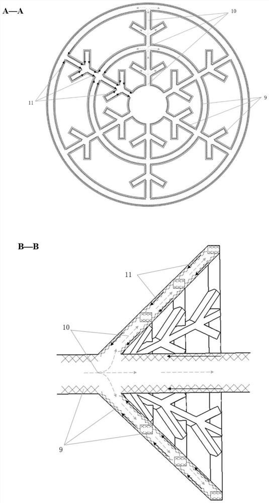
[0034] figure 1 with figure 2 It is a schematic structural diagram of a biomimetic phase transitional energy vapor chamber provided by the present invention.

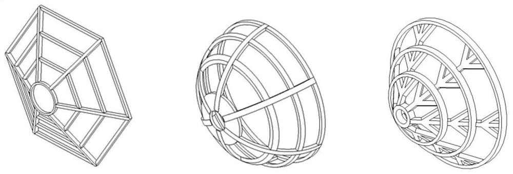
[0035] The present invention will be specifically described in conjunction with the accompanying drawings. A bionic phase transition storage vapor module, the overall structure is composed of a tree vapor cavity 2, a phase transform container 3, a tree vapor chamber 2, a phase change, a phase change container 3 filled a phase change material 12. The tree vapor chamber 2 includes at least one vapor chamber plate 4, a columnar vapor cavity 5, a plurality of emitted rigid steam cavity 6 and an annular vapor chamber rib 7 structure, from the ground to form a tree root, stem, bionic bionic structure feature. One side of the steam chamber flat plate 4 is in contact with the heat source 1, and the surface area is more than ten times the heat source 1, so that the heat of the heat source 1 is uniformly diffused to the surface of t...


PUM


Abstract

The invention relates to a bionic phase change energy storage steam cavity module which comprises a tree-shaped steam cavity and a phase change container. The tree-shaped steam cavity comprises at least one steam cavity flat plate, a columnar steam cavity and multiple groups of branch and trunk steam cavity structures. One surface of the steam cavity flat plate is in contact with a heat source so that heat concentrated by the heat source can be uniformly diffused to the surface of the steam cavity flat plate, and the other surface of the steam cavity flat plate is packaged with the outer surface of the phase change container. The columnar steam cavity is connected with the steam cavity flat plate, and the multiple groups of branch and trunk steam cavities are arranged around the columnar steam cavity and each provided with two or more branch and trunk steam cavity branches extending towards the space. The multiple groups of branch and trunk steam cavities are connected through multiple layers of annular steam cavity ribs. Internal channels of the steam cavity flat plate, the columnar steam cavity, the branch and trunk steam cavities and the annular steam cavity ribs are communicated with one another, the internal spaces are filled with phase change working media, and the inner surfaces are provided with porous capillary structures. The tree-shaped steam cavity structure is arranged in the phase change container, and other parts in the phase change container are filled with phase change materials.

Description

Technical field [0001] The present invention relates to the field of thermal management technology of electronic components, and more particularly to a high energy density high-efficiency heat dissipation system. Background technique [0002] There are three main heat storage technologies, including thermal storage, latent heat storage and thermochemical storage. The latent heat storage system has the characteristics of high energy storage density, small temperature variation, has been successfully applied to solar thermal utilization, industrial waste recycling, building energy saving, electronic equipment heat dissipation. However, the thermal conductivity of the phase change material used in the latent heat storage system will severely impair the storage and release rate of thermal energy. The enhancement method currently used can be divided into three types: one is to enhance the thermal conductivity of the phase change material using porous media and nanoparticles, such as f...

Claims


Application Information

Patent Timeline
IPC IPC(8): F28D15/04
CPCF28D15/043F28D15/046Y02E60/14
Inventor 褚雯霄何峻杰王秋旺曾敏
Owner XI AN JIAOTONG UNIV
Why Eureka
Try Eureka