Five-axis machine tool speed planning method based on S-shaped acceleration and deceleration

A speed planning, acceleration and deceleration technology, applied in the direction of instruments, digital control, control/regulation systems, etc., can solve the problems of affecting the surface quality of parts processing, increasing the complexity of the method, increasing the acceleration and deceleration time of machine tools, etc., to improve the processing efficiency of machine tools Effect

Pending Publication Date: 2021-07-23
XI AN JIAOTONG UNIV
View PDF0 Cites 3 Cited by
  • Summary
  • Abstract
  • Description
  • Claims
  • Application Information

AI Technical Summary

Problems solved by technology

In the related research of flexible acceleration and deceleration, it mainly includes: (1) The construction method of S-curve acceleration and deceleration is given by numerical method or analytical method, but when faced with high-speed, high-precision and high-curvature machining, the discrete small line segment is relatively short (2) By simplifying the S-curve acceleration and deceleration model to a 5-stage S-curve acceleration and deceleration model, the complexity of the model can be reduced. Although it can meet the requirements of flexible speed changes, it is not suitable for uniform acceleration and deceleration. Acceleration section can only reach the maximum feed rate
(3) Speed ​​control is carried out by using flexible acceleration and deceleration with jerk gradient to achieve continuous jerk, but the complexity of t

Method used


Image

  • Five-axis machine tool speed planning method based on S-shaped acceleration and deceleration
  • Five-axis machine tool speed planning method based on S-shaped acceleration and deceleration
  • Five-axis machine tool speed planning method based on S-shaped acceleration and deceleration

Examples


Embodiment Construction

[0133] The present invention will be described in detail below in conjunction with the accompanying drawings and embodiments.

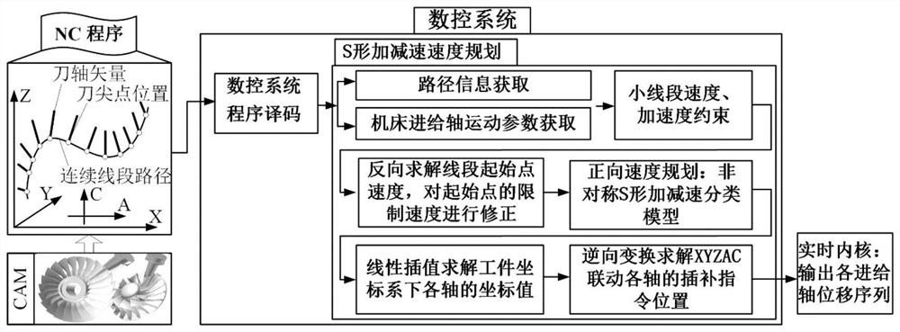
[0134] refer to figure 1 , a five-axis machine tool speed planning method based on S-shaped acceleration and deceleration, comprising the following steps:

[0135] Step 1) First obtain the path information of the continuous machining path, the motion parameters of each feed axis of the machine tool and the allowable interpolation error of the small line segment path, and obtain the small line segment speed, acceleration constraints;

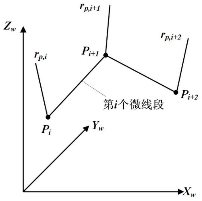
[0136] 1.1) figure 2 It is a schematic diagram of the tool tip point and the tool axis vector of the machining path. According to the part processing information provided in the G code, the tool position information of the part in the workpiece coordinate system is obtained. In the workpiece coordinate system, the tool path is composed of a series of continuous small line segments , where the point P i , P i+1 and ...


PUM


Abstract

The invention discloses a five-axis machine tool speed planning method based on S-shaped acceleration and deceleration. The method comprises the steps: obtaining the path information of a continuous machining path, and building a complete S-shaped acceleration and deceleration model; dividing an incomplete acceleration and deceleration process into a plurality of conditions, and establishing a corresponding acceleration and deceleration speed diagram planning method; then correcting the limiting speed of the starting point of the small line segment; determining acceleration and deceleration types which should be adopted by the current small line segments through the S-shaped acceleration and deceleration classification model, calculating displacement, speed and acceleration diagrams of the small line segments, and solving coordinate values of each axis under a workpiece coordinate system through linear interpolation; and finally, converting the coordinate value of each axis in each interpolation period in a workpiece coordinate system into the coordinate value of each axis in each interpolation period in a machine tool coordinate system by adopting reverse coordinate transformation, performing part processing, calculating the velocity diagram of each small line segment forwards segment by segment, and finally obtaining the interpolation instruction position and instruction speed on the whole processing path. High feeding speed can be achieved, and moving stability of moving parts of a machine tool is guaranteed.

Description

technical field [0001] The invention belongs to the technical field of interpolation methods of high-speed numerical control technology, and in particular relates to a five-axis machine tool speed planning method based on S-shaped acceleration and deceleration. Background technique [0002] Acceleration and deceleration control is an important part and one of the key technologies of the CNC system. During the motion control process of the CNC system, it plays an important role in ensuring the smooth movement of the moving parts of the machine tool, reducing the vibration during machine tool processing, and ensuring the processing quality of parts. effect. [0003] The relatively simple and commonly used acceleration and deceleration control methods mainly include linear and exponential acceleration and deceleration methods. The linear acceleration and deceleration method is easy to implement. In the exponential acceleration and deceleration method, the feed speed is acceler...

Claims


Application Information

Patent Timeline
IPC IPC(8): G05B19/416
CPCG05B19/4163G05B2219/36521Y02P90/02
Inventor 张星王增光赵万华马昂扬
Owner XI AN JIAOTONG UNIV
Why Eureka
Try Eureka