
Method and device for calculating vibration mode of multi-split conductor

A vibration mode and calculation method technology, applied in design optimization/simulation, special data processing applications, instruments, etc., can solve problems such as long wire lines and difficulties in carrying out true-type tests, and achieve the goal of improving calculation speed and fast and effective analysis Effect

Pending Publication Date: 2021-07-23
FOSHAN POWER SUPPLY BUREAU GUANGDONG POWER GRID
View PDF2 Cites 1 Cited by
  • Summary
  • Abstract
  • Description
  • Claims
  • Application Information

AI Technical Summary

Problems solved by technology

However, software simulation requires pre-modeling preparations, and can only calculate the vibration mode of a specific line; experimental research is difficult to carry out real-type tests because the wire line is too long

Method used


Image

  • Method and device for calculating vibration mode of multi-split conductor
  • Method and device for calculating vibration mode of multi-split conductor
  • Method and device for calculating vibration mode of multi-split conductor

Examples


Embodiment 1

[0136] Such as Figure 5 As shown, this embodiment provides a method for calculating the vibration mode of a multi-split wire, including:

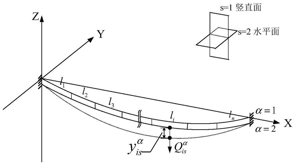
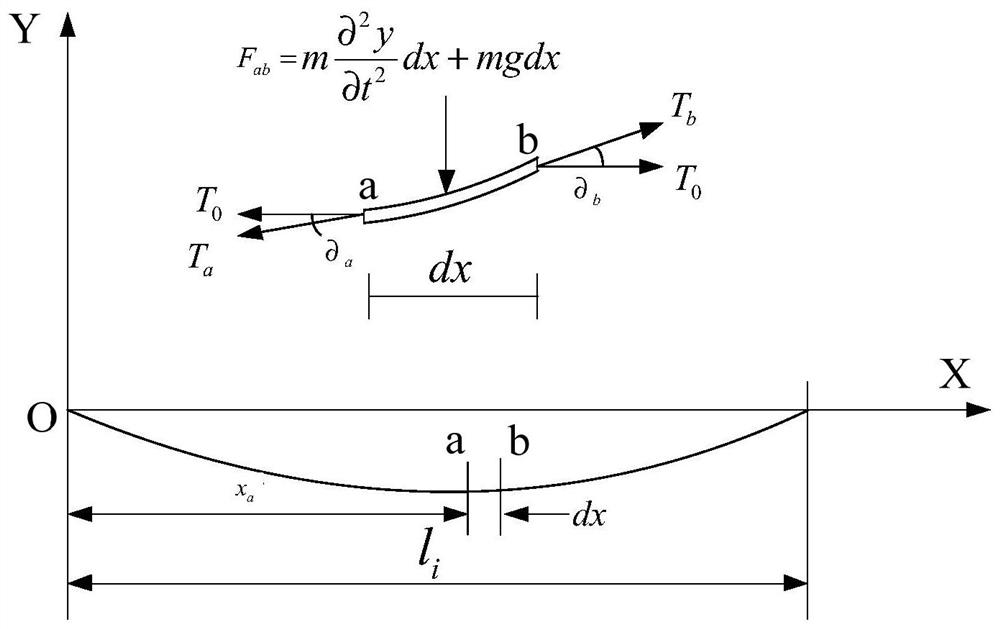
[0137] S1: Determine the parameters. The parameters include the mass per unit length of the multi-split wire, the wire tension during normal operation, the split spacing, the axial tension-compression stiffness and bending stiffness of the spacer, the number of sub-gages, and the length of each sub-gap.

[0138] In this embodiment, a 220kV double-split conductor is taken as an example. The double-split conductor model is LGJ-400 / 35, which is arranged vertically. The split distance (that is, the length of the spacer) is 0.4m. The axial tensile and compressive stiffness EA of the spacer is taken as 12000, the bending stiffness EI is 24. The wire parameters and secondary span data (including the number of secondary spans and the length of each secondary span) obtained in step S1 are shown in Tables 1 and 2 below:

[0139] Table 1 wire param...

Embodiment 2

[0180] Such as Figure 14 As shown, this embodiment provides a vibration mode calculation device for multi-split wires, including a parameter determination unit 1401, a parameter substitution unit 1402, a solving unit 1403 and a drawing unit 1404, wherein:

[0181] The parameter determination unit 1401 is used to determine the parameters. The parameters include the mass per unit length of the multi-split wire, the wire tension during normal operation, the split spacing, the axial tension-compression stiffness and bending stiffness of the spacer, the number of sub-gages, and each sub-gap. the length of the span;

[0182] The parameter substitution unit 1402 is used for substituting the mass per unit length and the wire tension during normal operation into the field transfer matrix used to represent the vibration characteristics in the sub-gap; The stiffness is substituted into the point transfer matrix used to represent the joint properties at the spacer installation;

[0183...


PUM


Abstract

The invention discloses a method and a device for calculating the vibration mode of a multi-split conductor. The method comprises the steps: employing a transfer matrix method, employing a field transfer matrix to represent the vibration characteristics in a subspan, employing a point transfer matrix to represent the connection characteristics of a spacer installation part, substituting the determined conductor parameters into the field transfer matrix and the point transfer matrix, and calculating the vibration mode of the multi-split conductor; and solving the vibration mode of the multi-split conductor by combining the field transfer matrix and the point transfer matrix into which the parameters are substituted and boundary conditions (i.e., the vibration displacement of the two end points is zero) to obtain the inherent frequency of each order of the multi-split conductor and a modal shape diagram corresponding to the inherent frequency, so as to quickly and accurately calculate the vibration mode of the multi-split conductor. The calculation speed of the multi-split conductor vibration mode is improved.

Description

technical field [0001] The invention relates to the technical field of electrical analysis of transmission lines, and more specifically, to a vibration mode calculation method and device for multi-split conductors. Background technique [0002] The mode of the structure, that is, the natural frequency and mode shape of the structure, is an important parameter in the design of the structure to withstand dynamic loads, and it is also the starting point for studying other dynamic problems. For the vibration modal analysis of a single-strand wire, the differential equation of motion is generally established for solution calculation. This method is simple, fast and widely recognized. However, in order to improve the power transmission capacity of the line, the lines with a voltage level of 220kV and above in my country generally use multi-split conductors. For multi-split conductors, due to the existence of spacers, the sub-conductors will interact with each other, thus forming ...

Claims


Application Information

Patent Timeline
Patent Type & Authority Applications(China)
IPC IPC(8): G06F30/20G06F119/14
CPCG06F30/20G06F2119/14
Inventor 徐振磊叶永强舒应军朱谦曾懿辉韩春雨
Owner FOSHAN POWER SUPPLY BUREAU GUANGDONG POWER GRID
Learn More