Driving backboard, manufacturing method thereof and light-emitting substrate

A technology for driving backplanes and substrate substrates, applied in electrical components, electrical solid-state devices, circuits, etc., can solve the problems of affecting Micro-LED transfer yield, low alignment accuracy, etc.

Pending Publication Date: 2021-07-23
BOE TECH GRP CO LTD +1
View PDF0 Cites 1 Cited by
  • Summary
  • Abstract
  • Description
  • Claims
  • Application Information

AI Technical Summary

Problems solved by technology

[0004] However, due to various reasons such as equipment, materials, substrates, and transfer methods, the alignment accu

Method used


Image

  • Driving backboard, manufacturing method thereof and light-emitting substrate
  • Driving backboard, manufacturing method thereof and light-emitting substrate
  • Driving backboard, manufacturing method thereof and light-emitting substrate

Examples


Embodiment Construction

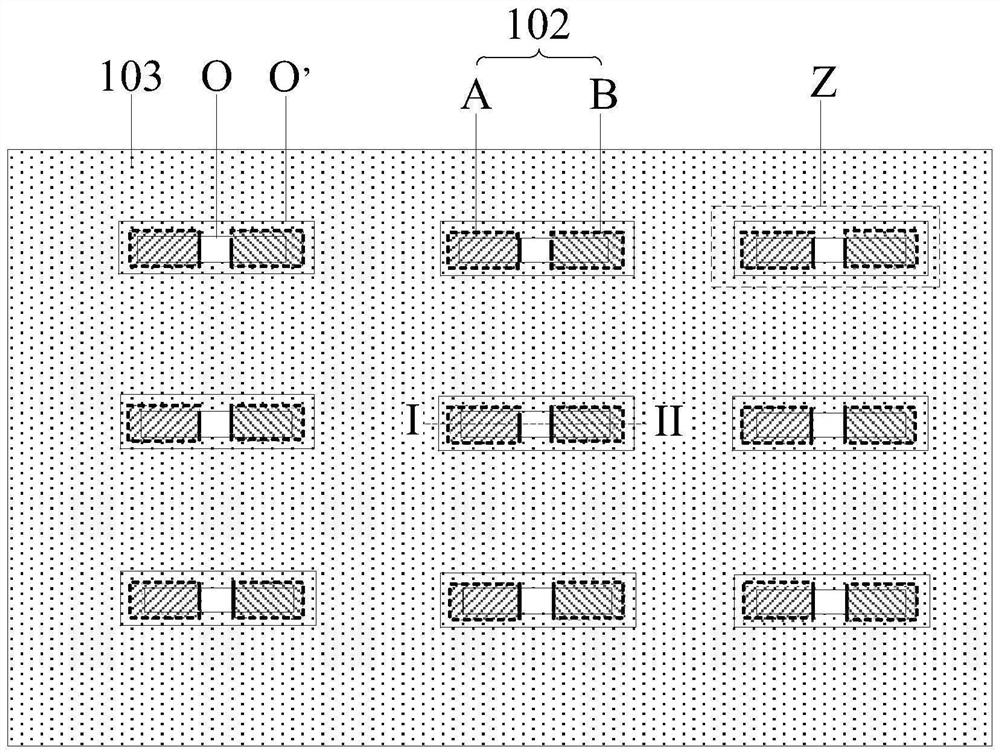
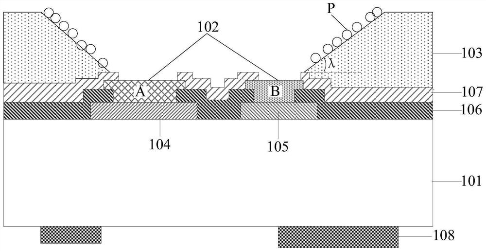
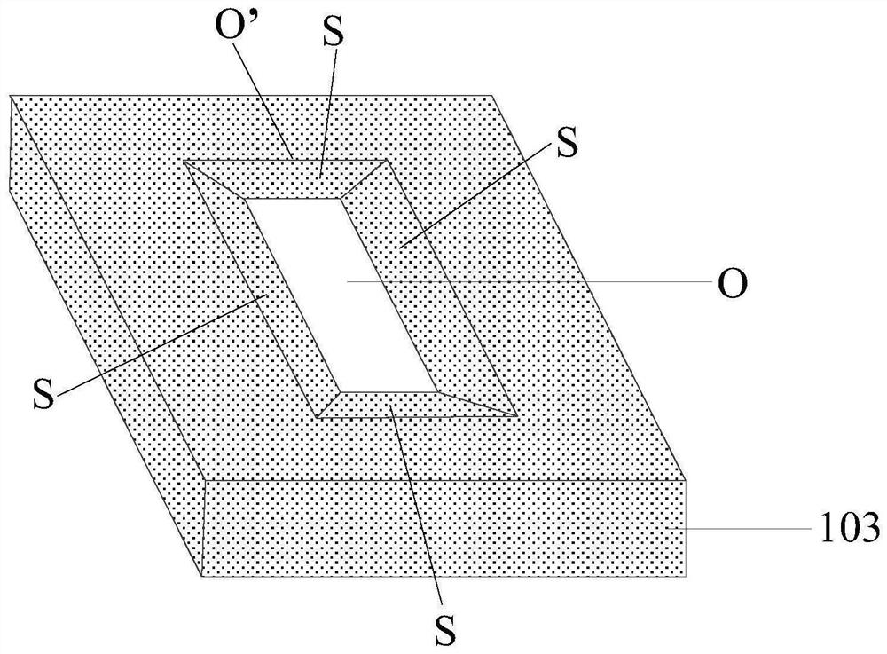
[0044]In order to make the purpose, technical solutions and advantages of the embodiments of the present invention more clear, the following will clearly and completely describe the technical solutions of the embodiments of the present invention in conjunction with the drawings of the embodiments of the present invention. It should be noted that the size and shape of each figure in the drawings do not reflect the actual scale, but are only intended to schematically illustrate the content of the present invention. And the same or similar reference numerals represent the same or similar elements or elements having the same or similar functions throughout. Apparently, the described embodiments are some, not all, embodiments of the present invention. Based on the described embodiments of the present invention, all other embodiments obtained by persons of ordinary skill in the art without creative efforts shall fall within the protection scope of the present invention.

[0045] Un...


PUM


Abstract

The invention provides a driving backboard, a manufacturing method thereof and a light-emitting substrate. The driving backboard comprises an underlayment substrate, a plurality of connecting electrode groups, and a shading layer. The plurality of connecting electrode groups are positioned on the substrate, and each connecting electrode group is used for being connected with one light-emitting element in a binding manner. Each connecting electrode group comprises a first connecting electrode and a second connecting electrode. The shading layer is positioned on a layer on which the plurality of connecting electrode groups are positioned. First openings are formed in the surface, close to the underlayment substrate, of the shading layer, second openings are formed in the surface, away from the underlayment substrate, of the shading layer, the first openings and the second openings are communicated, and the first openings are larger than the second openings. The first openings expose at least part of the surfaces of the first connecting electrodes and at least part of the surfaces of the second connecting electrodes. The shading layer further comprises a side face connecting the surface, close to the underlayment substrate, of the shading layer and the surface, away from the underlayment substrate, of the shading layer, the side face is a rough face, and the included angle between the side, away from the connecting electrode groups, of the side face and the plane where the underlayment substrate is located is an acute angle.

Description

technical field [0001] The invention relates to the field of display technology, in particular to a driving backplane, a manufacturing method thereof and a light-emitting substrate. Background technique [0002] Micro-LED display panels have the characteristics of ultra-high pixel count, ultra-high resolution, low energy consumption, and long life. Micro-LED technology is a miniaturized and matrixed micro-sized LED array, which consumes less power. Compared with organic electroluminescent diodes (OLEDs), it can reduce the distance between pixels from millimeters to microns, and the color gamut higher. [0003] The related technology uses micro-transfer printing to make Micro-LED arrays. After the Micro-LEDs are separated from the sapphire substrate by laser lift-off technology, a patterned transfer substrate is used to absorb the Micro-LEDs from the supply substrate, and then transfer them to The driving backplane is a silicon substrate with pre-prepared circuit patterns. ...

Claims


Application Information

Patent Timeline
IPC IPC(8): H01L27/12H01L25/075H01L33/48H01L33/58H01L33/60H01L33/62
CPCH01L25/0753H01L27/124H01L33/486H01L33/58H01L33/60H01L33/62H01L2933/0033H01L2933/0058H01L2933/0066
Inventor 齐永莲赵合彬邱云曲连杰张珊石广东
Owner BOE TECH GRP CO LTD
Why Eureka
Try Eureka