Wireless charging equipment, automatic alignment method and charging base

A technology for wireless charging equipment and electronic equipment, applied in electric vehicles, battery circuit devices, current collectors, etc., can solve the problems of inability to align the position of the receiving coil and the transmitting coil, and the inability to charge and charge efficiency, and to increase the degree of freedom of charging , to achieve the effect of automatic alignment

Pending Publication Date: 2021-07-23
HUAWEI DIGITAL POWER TECH CO LTD
View PDF5 Cites 2 Cited by
  • Summary
  • Abstract
  • Description
  • Claims
  • Application Information

AI Technical Summary

Problems solved by technology

For example, when the electronic device is a mobile phone or a wearable device, the position of the receiving coil and the transmitting coil may not be aligned when the electronic device is placed on a wireless charging device, so charging may not be possible or the charging efficiency may be low

Method used


Image

  • Wireless charging equipment, automatic alignment method and charging base
  • Wireless charging equipment, automatic alignment method and charging base
  • Wireless charging equipment, automatic alignment method and charging base

Examples


Embodiment 1

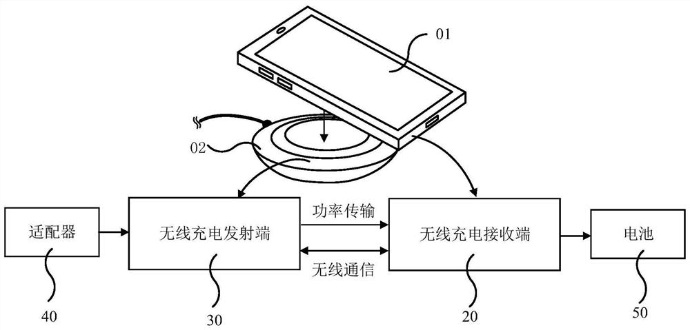
[0097] see Figure 5A , which is a schematic diagram of a wireless charging device provided in an embodiment of the present application.

[0098] For the convenience of understanding, the wireless charging device provided in the embodiment of the present application is described by taking a wireless charger, that is, a wireless charging base as an example. The wireless charging device can charge an electronic device, and the electronic device is a mobile phone as an example for description.

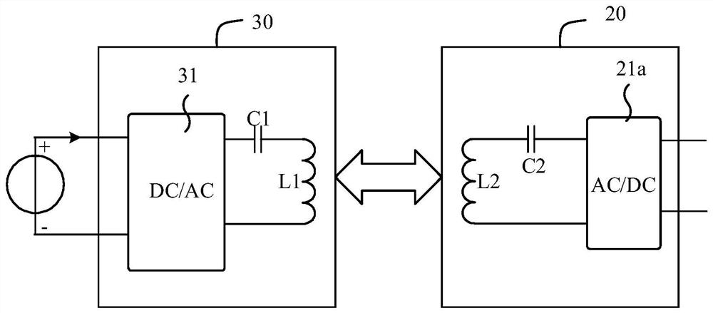
[0099] The wireless charging device provided in the embodiment of the present application includes: a transmitting coil L1, a controller 32 and at least two detecting coils; Figure 5A In the description, the detection coil includes at least two of the following as an example for description: a first detection coil L11 and a second detection coil L12. It should be understood that at least two detection coils can also be referred to as a detection coil array.

[0100] The first detectio...

Embodiment 2

[0131] An implementation manner in which a plurality of detection coils are connected to an excitation power supply is described below in conjunction with the accompanying drawings.

[0132] see Figure 6A , which is a schematic diagram of another wireless charging device provided in the embodiment of the present application.

[0133] Based on the first embodiment of the wireless charging device, before wireless charging, there may be foreign objects between the wireless charging device and the electronic device, for example: metal foreign objects, the changing magnetic field generated between the transmitting coil L1 and the receiving coil Eddy current losses and heat are generated. Therefore, before wireless charging, the Q value of each detection coil can also be obtained. When the Q value of the detection coil is less than or equal to the preset Q value, it is determined that there is a metal foreign object between the transmitting coil L1 and the receiving coil. In orde...

Embodiment 3

[0155] In the embodiment of the present application, the parameters obtained by the controller 32 may also be the communication results of each detection coil and receiving coil, and control the transmitting coil L1 to move in the direction corresponding to the detection coil whose communication result is a successful communication.

[0156]Among them, in the wireless charger standard, the successful communication refers to the successful ping, which can be successfully pinged in the "pingable area". High enough so that the circuit at the receiving end can start to work. The area where the transmitting coil is located at this time is called the "pingable area". The information of the coupling strength of the coil is called the signal strength packet in the Qi standard. The signal strength package represents the size of the coupling strength, which is actually represented by the output voltage of the rectifier circuit in the electronic device; the higher the output voltage, the...


PUM


Abstract

The invention discloses wireless charging equipment, an automatic alignment method and a charging base. The wireless charging equipment comprises a transmitting coil, a controller and at least two detection coils, wherein the at least two detection coils are located on one side of the plane where the transmitting coil is located, and the plane where the detection coils are located is parallel to the plane where the transmitting coil is located; and the controller is used for respectively controlling the at least two detection coils to be sequentially connected with the excitation power supply, acquiring parameters of the detection coils connected with the excitation power supply, and controlling the transmitting coil to move according to the size difference of the parameters between the at least two detection coils, so that the transmitting coil is aligned with a receiving coil in the electronic equipment. The sum of the coverage area of the plurality of detection coils is larger than the coverage area of the transmitting coil, so that the position of the receiving coil is judged by using the parameters of the detection coils, the transmitting coil is controlled to move to realize alignment with the receiving coil, the range for receiving the placement of the electronic equipment is larger, the charging freedom degree is increased, and the wireless charging experience of the user is improved.

Description

technical field [0001] The embodiments of the present application relate to the technical field of wireless charging, and in particular, to a wireless charging device, an automatic alignment method, and a charging base. Background technique [0002] Wireless charging technology (wireless charging technology, WCT) uses conductive media such as electric fields, magnetic fields, microwaves or lasers to realize wireless transmission of electric energy. Due to its advantages of no wire restrictions, no plugging and unplugging, it is currently more and more used in electronic devices. more extensive. Currently, more and more electronic devices use wireless charging devices to wirelessly charge them, for example, electronic devices may be mobile phones, wearable devices, and the like. A wireless charging device includes a transmitting coil, and an electronic device includes a receiving coil. [0003] At present, wireless charging technology transmits energy through magnetic field...

Claims


Application Information

Patent Timeline
Patent Type & Authority Applications(China)
IPC IPC(8): H02J50/12H02J50/60H02J50/70H02J50/90H02J7/02
CPCH02J50/12H02J50/60H02J50/70H02J50/90H02J7/02H02J50/005Y02B40/00H02J50/40
Inventor 吴宝善吴东昊
Owner HUAWEI DIGITAL POWER TECH CO LTD
Why Eureka
Try Eureka