Bidirectional simultaneous rotary blade bundle for mixer

A technology of rotating blades and mixers, applied in mixer accessories, mixers with rotating mixing devices, applications, etc., can solve the problems of rotation effectiveness, rotation stability and reliability, increase in blade bundle volume, increase in the number of assembly processes, etc. problems, to achieve the effect of reducing the number of parts and assembly processes, reducing manufacturing costs, and saving costs

Pending Publication Date: 2021-07-23
CUCKOO ELECTRONICS CO LTD
View PDF8 Cites 1 Cited by
  • Summary
  • Abstract
  • Description
  • Claims
  • Application Information

AI Technical Summary

Problems solved by technology

[0009] In the arrangement structure of the driven gear mentioned above, due to the eccentricity of the power transmission process in the reverse direction, the overall rotation can only be eccentric to one side. As a result, problems of rotation efficiency, rotation stability and reliability may occur, and further noise problem
[0010] In addition, in the technology of the above-mentioned Patent No. 10-1862587, in order to transmit the rotational force of the driving gear to the counter-rotating rotor, a total of three steps of power transmission steps, such as the driven gear and the counter-rotating gear, are required, and, Only counter-rotating gears screwed to the counter-rotating rotor can be selected
[0011] As described above, the number of assembly steps will increase due to the increase in the number of parts due to the large number of gears occupying a large volume in the horizontal and vertical directions. There is a problem that the volume will increase, so there is a problem that hinders the miniaturization of the product

Method used


Image

  • Bidirectional simultaneous rotary blade bundle for mixer
  • Bidirectional simultaneous rotary blade bundle for mixer
  • Bidirectional simultaneous rotary blade bundle for mixer

Examples


Embodiment Construction

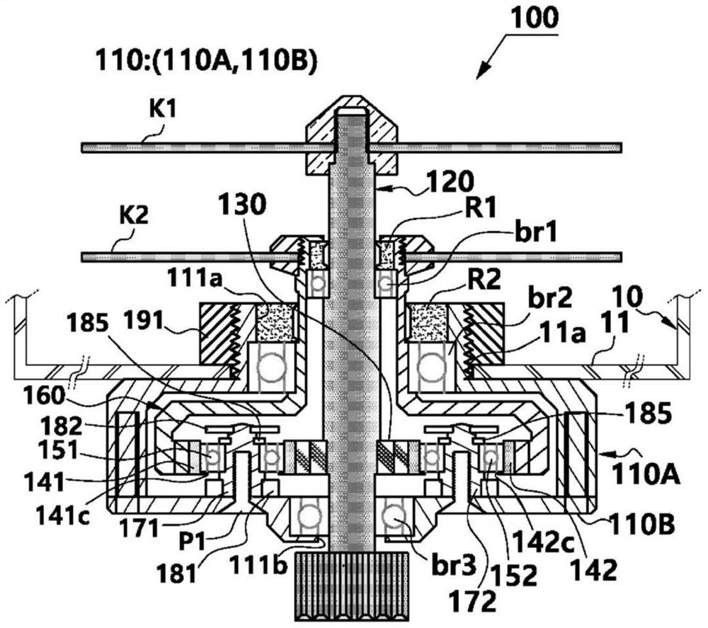
[0036] Hereinafter, preferred embodiments of the bidirectional simultaneous rotating blade bundle for a mixer of the present invention will be described in detail with reference to the drawings.

[0037]The present invention relates to a blender, and the blender includes: a cylindrical container 10 for holding food such as fruits, meat, vegetables, coffee, grains, etc.; Combination; motor (not shown), built in the motor housing (not shown), so as to be able to rotate inside the motor housing; and the blade bundle 100, receiving the rotational force of the motor, rotating according to the rotation of the motor to cut , crushing, grinding the food in the container 10, especially, the present invention relates to the blade bundle 100 as the core structure of the blender.

[0038] The container, the motor housing, and the motor itself are known structures before the application of the present invention, and therefore, detailed description thereof will be omitted.

[0039] As show...


PUM


Abstract

The present invention relates to a bidirectional simultaneous rotary blade bundle for a mixer, the bidirectional simultaneous rotary blade bundle comprising: a housing (110); a forward rotary shaft (120) installed on the housing (110); a forward rotation blade (K1) provided on the forward rotary shaft (120); a central gear (130) axially installed on the forward rotary shaft (120); horizontal insertion gears (141, 142, and 143) engaged with the central gear (130); a reverse rotor (160), of which inner gear teeth (164) are engaged with and rotate on the outside of the horizontal insertion gears (141, 142, and 143); and a reverse rotation blade (K2) installed on the reverse rotor (160), wherein the horizontal insertion gears (141, 142, and 143) are rotated in the reverse direction according to the forward rotation of the central gear (130) to forcibly rotate the inner gear teeth (164) in the reverse direction.

Description

technical field [0001] The present invention relates to mixers. Background technique [0002] Generally, a blender is an electric machine that can be ingested in various forms by chopping, stirring, mixing, cutting (cutting) or crushing (hereinafter, collectively referred to as "crushing") fruits and vegetables, grains and the like. equipment. [0003] Basically, the blender may include: a motor housing with a built-in motor; a container combined with the motor housing and having a rotary blade receiving rotational force from the motor; and a cap for opening and closing the upper end of the container. [0004] The above-mentioned rotary blade formed inside the above-mentioned container may be attached to the rotation shaft of the blade bundle. [0005] As a prior art related to such a blade bundle, there is disclosed the Korean Granted Patent No. 10-1862587 (publication date: May 31, 2018) of "Bidirectional Simultaneously Rotating Blades for Blender" which was applied for ...

Claims


Application Information

Patent Timeline
Patent Type & Authority Applications(China)
IPC IPC(8): A47J43/07B26D1/28B26D5/08B26D7/26
CPCA47J43/0722A47J43/085B01F27/84B01F27/808B01F35/33B26D1/28B26D5/086B26D7/2614
Inventor 金英珍
Owner CUCKOO ELECTRONICS CO LTD
Why Eureka
Try Eureka