
Magnetic-inductive flow meter and measuring point

A flowmeter and magnetic induction technology, which is applied in the field of magnetic induction flowmeters and measurement points, can solve problems such as unclear

Pending Publication Date: 2021-07-23
ENDRESS HAUSER FLOWTEC AG
View PDF12 Cites 0 Cited by
  • Summary
  • Abstract
  • Description
  • Claims
  • Application Information

AI Technical Summary

Problems solved by technology

[0010] The disadvantage of these proposals is that weighting factors have to be considered for each electrode pair, and it is not clear how to choose these weighting factors according to the flow profile of the piping system or rotational asymmetry

Method used


Image

  • Magnetic-inductive flow meter and measuring point
  • Magnetic-inductive flow meter and measuring point
  • Magnetic-inductive flow meter and measuring point

Examples


Embodiment Construction

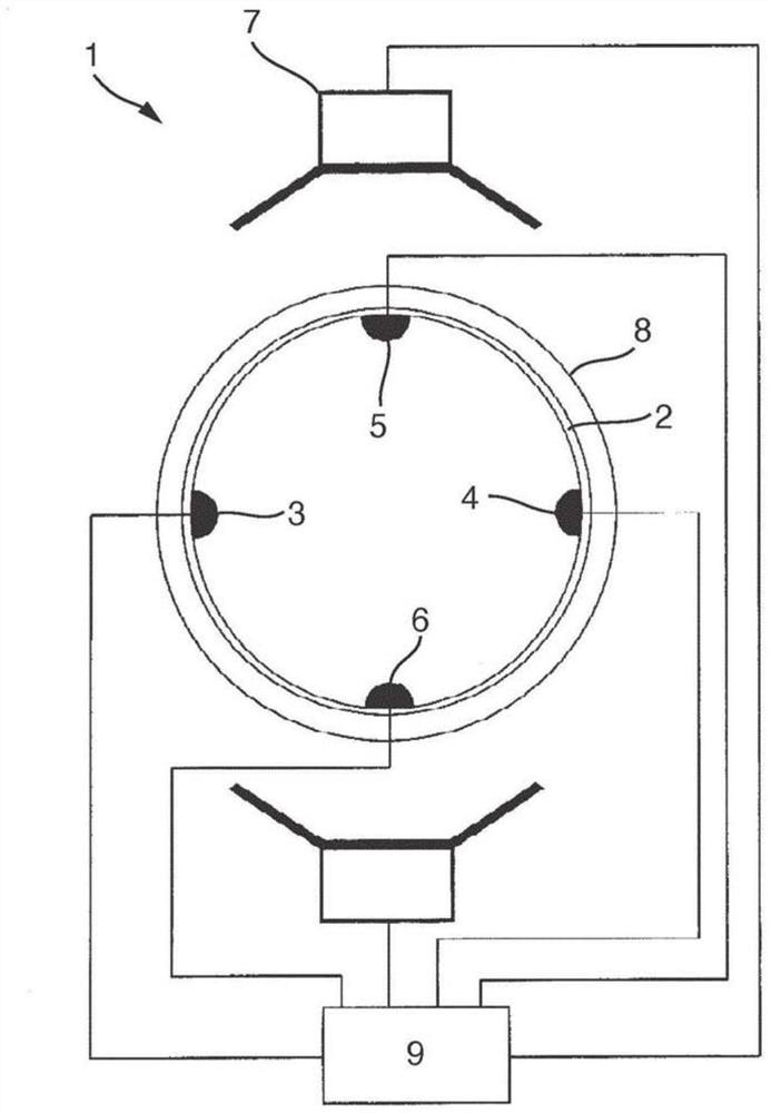
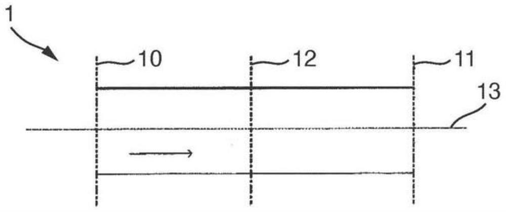
[0061] figure 1A magnetic induction flowmeter known in the prior art is shown. The construction and measurement principles of magnetic induction flowmeters are basically known. The conductive medium is led through the measuring tube (1). The magnetic field generating means (7) are arranged such that the magnetic field lines extend perpendicular to the longitudinal direction defined by the measuring tube axis (13). Preferably suitable as magnetic field generating means (7) are saddle coils or pole shoes (26) with overlapping coils and coil cores. When a magnetic field is applied, a flow-dependent potential distribution is generated in the measuring tube (1), which is sensed with two electrodes (3, 4) applied at the inner surface of the measuring tube (1). Typically, they are arranged diametrically opposite each other and form an electrode axis extending perpendicular to the magnetic field lines and to the longitudinal axis of the tube. Based on the measured voltage and taki...


PUM


Abstract

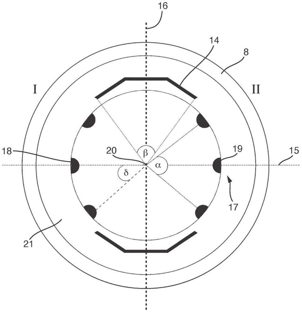
The invention relates to a magnetic-inductive flow meter for measuring the flow velocity or the volumetric flow rate of a medium, comprising: a measurement tube having a first cross-section, for conducting the medium, wherein the measurement tube has a center segment between the end face on the inlet side and the end face on the outlet side, which segment has a second cross-section, wherein the first cross-sectional area is larger than the second cross-sectional area; at least one magnetic-field-generating apparatus for generating a magnetic field, which is substantially perpendicular to the longitudinal direction, in the medium, wherein the magnetic-field-generating apparatus has a pole shoe or a saddle coil, wherein the pole shoe or the saddle coil surrounds the fluid-conducting channel at a maximum center-point angle beta in the second cross-section of the measurement tube; and an electrode system having at least two electrode pairs, which are designed to detect a voltage between the electrode pairs which is induced perpendicularly to the magnetic field and to the longitudinal direction. A first electrode of each electrode pair is located on the first side of the measurement tube and a second electrode of each electrode pair is located on the second side. A center-point angle a impinges a minimum circle sector in the second cross-section of the measurement tube, in which segment the electrodes located on each side of the measurement tube are distributed. The electrode pairs are arranged in the center segment. The magnetic-inductive flow meter is characterized in that the center-point angles alpha and beta are coordinated with one another such that the flow meter is insensitive to deviations of a rotationally symmetrical flow.

Description

Background technique [0001] A magnetic induction flowmeter is used to determine the flow velocity and / or volumetric flow rate of the medium in the measuring tube. Magnetic-inductive flowmeters include a magnetic field generating device that generates a magnetic field perpendicular to the transverse axis of the measuring tube. For this, usually one or more coils are used. In order to implement a predominantly homogeneous magnetic field, the saddle coils or pole shoes are additionally formed and positioned such that the magnetic field lines extend over the entire tube cross-section substantially perpendicular to the transverse axis. A pair of measuring electrodes located at the wall of the measuring tube senses an induced electrical measuring voltage which is generated when a conductive medium flows in the direction of the longitudinal axis in the presence of a magnetic field. Since the recorded measuring voltage depends on the velocity of the flowing medium, the flow velocity...

Claims


Application Information

Patent Timeline
IPC IPC(8): G01F1/58
CPCG01F1/588
Inventor 西蒙·玛利亚格
Owner ENDRESS HAUSER FLOWTEC AG
Learn More