Tetrode extraction apparatus for ion source

A technology of ion source and source electrode, applied in the direction of ion beam tube, discharge tube, electrical components, etc., can solve problems and other problems

A technology of ion source and source electrode, applied in the direction of ion beam tube, discharge tube, electrical components, etc., can solve problems and other problems

CN113169004APending Publication Date: 2021-07-23AXCELIS TECHNOLOGIES

Image

  • Tetrode extraction apparatus for ion source
  • Tetrode extraction apparatus for ion source
  • Tetrode extraction apparatus for ion source

Examples


Embodiment Construction

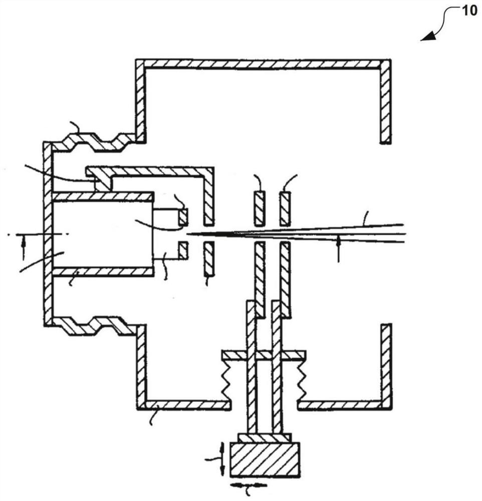
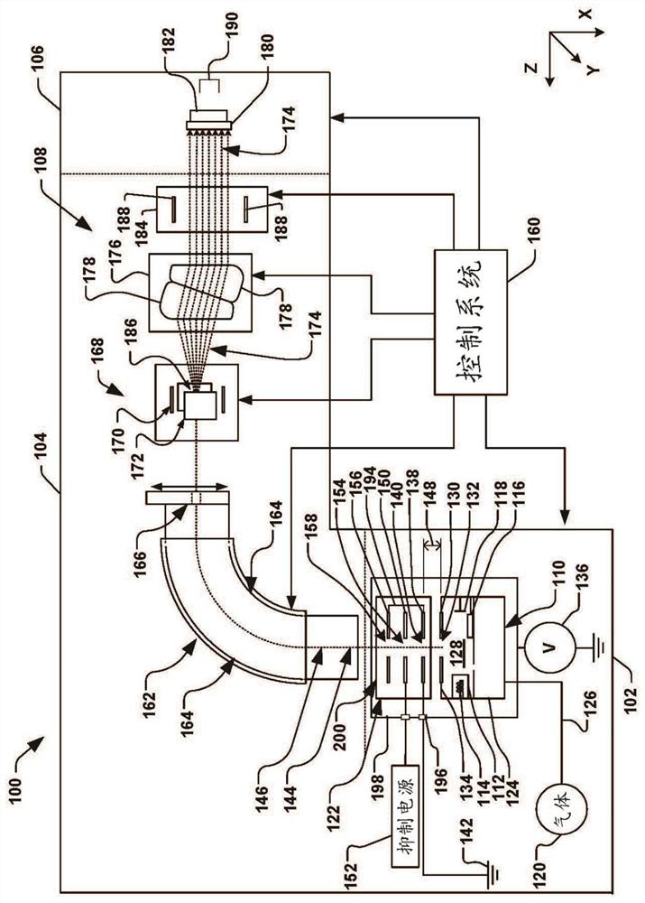
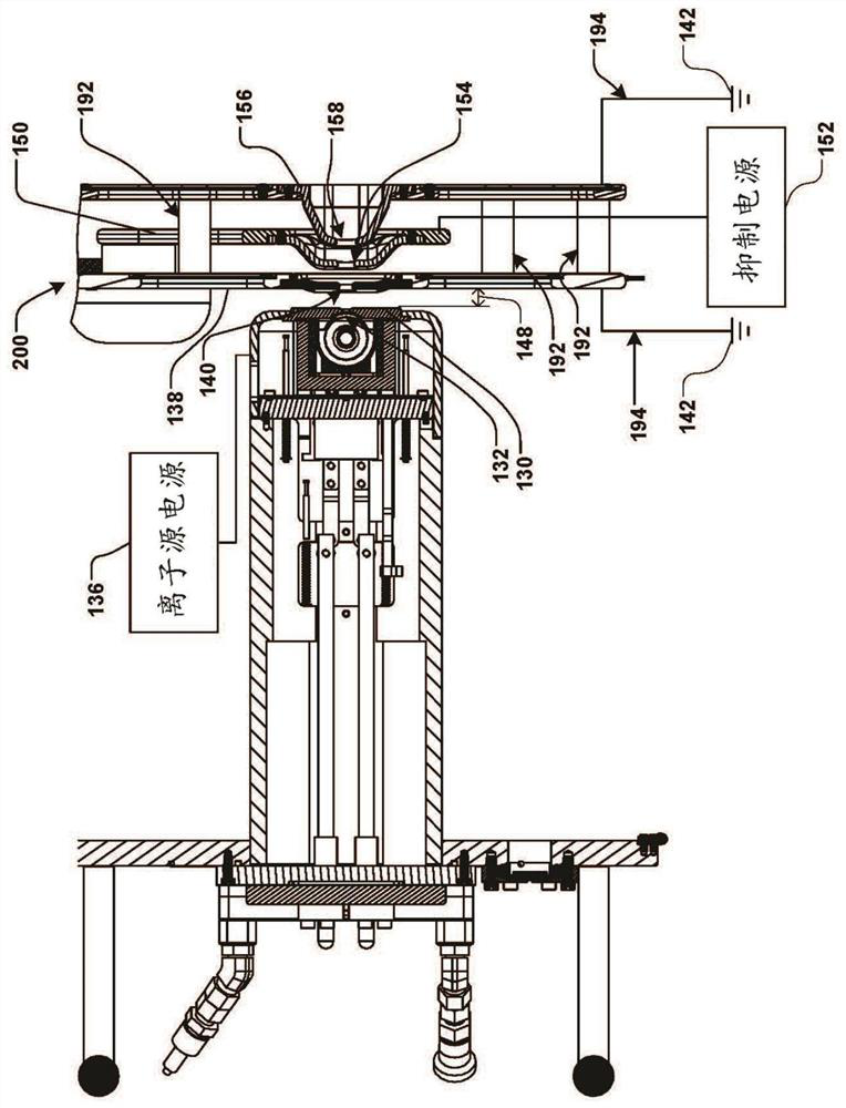
[0024] The present invention generally relates to an improved ion extraction electrode apparatus, system and method for an ion implantation system. Accordingly, the present invention will now be described with reference to the drawings, wherein like reference numerals may be used to refer to like elements throughout. It should be understood that the descriptions in these aspects are illustrative only, and they should not be interpreted in a limiting sense. In the following description, for purposes of explanation, numerous specific details are set forth in order to provide a thorough understanding of the present invention. It will be apparent, however, to one skilled in the art that the present invention may be practiced without these specific details. Furthermore, the scope of the present invention is not intended to be limited by the embodiments or examples described below with reference to the accompanying drawings, but is intended to be limited only by the appended claims...


PUM


Abstract

An electrode system for an ion source has a source electrode that defines a source aperture in an ion source chamber, and is coupled to a source power supply. A first ground electrode defines a first ground aperture that is electrically coupled to an electrical ground potential and extracts ions from the ion source. A suppression electrode is positioned downstream of the first ground electrode and defines a suppression aperture that is electrically coupled to a suppression power supply. A second ground electrode is positioned downstream of the suppression electrode and defines a second ground aperture. The first and second ground electrodes are fixedly coupled to one another and are electrically coupled to the electrical ground potential.

Description

[0001] References to related applications [0002] This application claims the benefit of U.S. Application Serial No. 16 / 227,296, entitled "Tetrode Extraction Apparatus for Ion Sources," filed December 20, 2018, the contents of which are hereby incorporated by reference in their entirety. technical field [0003] The present invention relates generally to ion implantation systems, and more particularly to a tetrode extraction apparatus with a ground-suppress-ground electrode having an ion source for a high current ion implanter. Background technique [0004] In the manufacture of semiconductor devices and other ion-related products, ion implantation systems are used to impart dopant elements into semiconductor wafers, display panels, or other types of workpieces. A typical ion implantation system or ion implanter strikes a workpiece with an ion beam using known recipes or processes to create n-type or p-type doped regions, or to form a passivation layer in the workpiece. W...

Claims


Application Information

Patent Timeline
23 Jul 2021
Publication
CN113169004A
IPC
H01J27/02; H01J37/317; H01J37/08
CPC
H01J27/024; H01J37/3171; H01J37/08; H01J2237/082; H01J2237/0817; H01J2237/0815; H01J2237/08; H01J2237/31701
Inventors
威廉·普拉托维; 爱德华·艾伊斯勒