Method for repairing coated components using NiAl bond coats

a coating and coating technology, applied in the direction of solid-state diffusion coating, superimposed coating process, machines/engines, etc., can solve the problems that affect the efficiency of the turbine, and achieve the effect of increasing the subsequent engine operation efficiency

Inactive Publication Date: 2006-08-22
GENERAL ELECTRIC CO
View PDF35 Cites 21 Cited by
  • Summary
  • Abstract
  • Description
  • Claims
  • Application Information

AI Technical Summary

Benefits of technology

[0014]In one embodiment of the invention, a method for repairing a coated component, which has been exposed to engine operation, to restore coated dimensions of the component and increase subsequent engine operation efficiency, is disclosed. The method comprises providing an engine run component including a base metal substrate. The base metal substrate has thereon a thermal barrier coating system comprising a bond coat on the base metal substrate and a top ceramic thermal barrier coating. The top ceramic thermal barrier coating has a nominal thickness t. The method further comprises removing the thermal barrier coating system, wherein a portion of the base metal substrate also is removed, and determining the thickness of the removed base metal. The portion of the base metal substrate removed has a thickness, Δt. A β-phase NiAl overlay bond coat is applied to the substrate, and the difference in thickness, Δx, between the β phase NiAl overlay coating (xNiAl) and the bond coat (xAdd) previously removed is determined (e.g. Δx=xNiAl−xadd). The method further comprises reapplying a top ceramic thermal barrier coating to a nominal thickness of t+Δt−Δx, where Δt compensates for the portion of removed base metal substrate. Advantageously, the dimensions of the coated component are restored to about the coated dimensions preceding the engine run to increase subsequent engine operation efficiency.
[0016]Applicants have determined how to provide further temperature reductions for airfoils, which increases ceramic spallation life, which lowers subsequent coating growth to be experienced in the next repair cycle, and which also provides further alloy mechanical property advantages. This may be achieved through the addition of TBC (Δt−Δx).
[0018]Applicants also have determined how to compensate for base metal loss as a result of coating removal processes, and also restore airfoil section contour to its pre-repair or original coated airfoil contour dimensions, without a weight penalty. Thus, an important advantage of embodiments of the invention is that resulting airfoil throat area restoration will allow the turbine to run much more efficiently. For example, during conventional repair of an engine run component, about 3 mils of underlying base metal thickness may be removed in the process. Thus, about a 3 mil loss of base metal may be experienced on both the pressure and suction side of an airfoil, which translates into about a 6 mil increase in throat dimension (distance between adjacent airfoil sections in an engine). While this increase in gap between the components may not adversely affect the mechanical operation of the engine, Applicants have determined that operation efficiency may be substantially adversely affected. Embodiments of Applicants' invention present an innovative, much needed solution to the above problem, which is inexpensive to implement and does not require additional costly equipment. Moreover, replacement of the prior bond coat with the afore-referenced NiAl-based overlay bond coat provides even further property improvements for embodiments of the invention.

Problems solved by technology

Applicants also have determined that such changes in airfoil dimension may substantially affect turbine efficiency.

Method used


Image

  • Method for repairing coated components using NiAl bond coats
  • Method for repairing coated components using NiAl bond coats
  • Method for repairing coated components using NiAl bond coats

Examples


Embodiment Construction

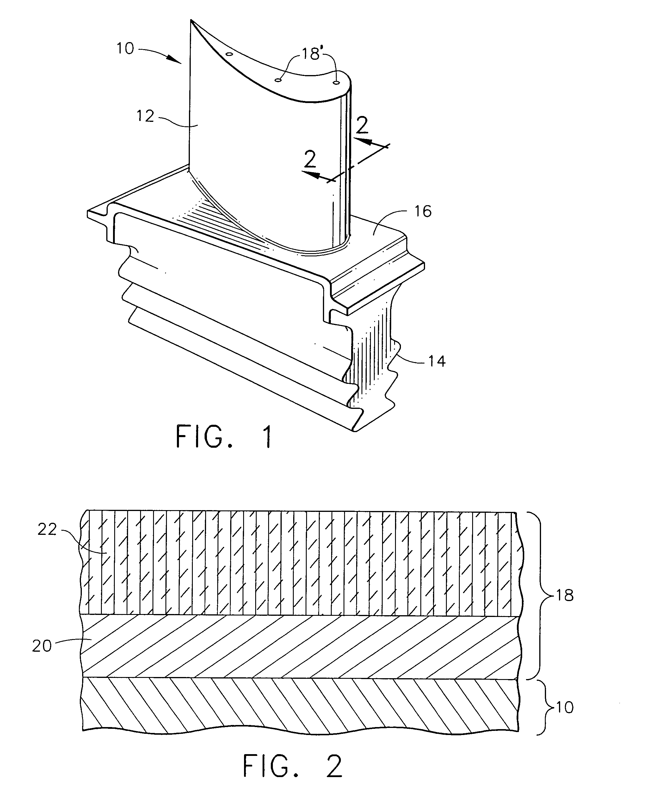
[0023]The repair method of the present invention is generally applicable to components that operate within environments characterized by relatively high temperatures, and are therefore subjected to severe thermal stresses and thermal cycling. Notable examples of such components include the high and low pressure turbine nozzles and blades, shrouds, combustor liners and augmentor hardware of gas turbine engines. Other examples include airfoils, in general, and static parts such as vanes. One particular example is the high pressure turbine blade 10 shown in FIG. 1. For convenience, the method of the present invention will be described in the context of repairing blade 10. However, one skilled in the art will recognize that the method described below may be readily adapted to repairing any other gas turbine engine part coated with a thermal barrier coating system.

[0024]The blade 10 of FIG. 1 generally includes an airfoil 12 against which hot combustion gases are directed during operatio...


PUM

PropertyMeasurementUnit
thicknessaaaaaaaaaa
densityaaaaaaaaaa
densityaaaaaaaaaa

Abstract

According to an embodiment of the invention, a method for repairing a coated high pressure turbine blade, which has been exposed to engine operation, to restore coated airfoil contour dimensions of the blade, and improve upon the prior bond coat is disclosed. The method comprises providing an engine run high pressure turbine blade including a base metal substrate made of a nickel-based alloy and having thereon a thermal barrier coating system. The thermal barrier coating system comprises a diffusion bond coat on the base metal substrate and a top ceramic thermal barrier coating comprising a yttria stabilized zirconia material. The top ceramic thermal barrier coating has a nominal thickness t. The method further comprises removing the thermal barrier coating system, wherein a portion of the base metal substrate also is removed, and determining the thickness of the base metal substrate removed. The portion of the base metal substrate removed has a thickness, Δt. The method also comprises applying a β phase NiAl overlay coating to the substrate, and determining the difference in thickness, Δx, between the β phase NiAl overlay coating and the previously removed bond coat. The method further comprises reapplying the top ceramic thermal barrier coating to a nominal thickness of t+Δt−Δx, wherein Δt compensates for the portion of removed base metal substrate. Advantageously, the coated airfoil contour dimensions of the high pressure turbine blade are restored to about the coated dimensions preceding the engine run.

Description

CROSS-REFERENCE TO RELATED APPLICATION[0001]The subject application shares certain attributes with U.S. Serial Nos. entitled, Method for Repairing Coated Components and Method for Repairing Components Using Environmental Bond Coatings and Resultant Repaired Components, respectively, filed concurrently herewith.FIELD OF THE INVENTION[0002]The invention generally relates to a method for repairing coated components exposed to high temperatures during, for example, gas turbine engine operation. More particularly, the invention relates to a method for removing and refurbishing a thermal barrier coating system that includes an inner metallic bond coat and an outer thermal insulating ceramic layer.BACKGROUND OF THE INVENTION[0003]Higher operating temperatures for gas turbine engines are continuously sought in order to increase efficiency. However, as operating temperatures increase, the high temperature durability of the components within the engine must correspondingly increase.[0004]Sign...

Claims


Application Information

Patent Timeline
Patent Type & Authority Patents(United States)
IPC IPC(8): B05C13/00B05D1/36F01D5/28B23P6/00C23C4/08C23C10/02C23C10/08C23C10/60C23C14/16C23C16/20C23C28/00C23C30/00C25D3/50C25D7/00F02C7/00
CPCB23P6/002C23C10/02C23C10/60C23C28/321C23C28/3215C23C28/3455C25D7/008C25D7/00C23C28/345C23C28/36F05B2230/31F05B2230/90F05C2253/12C25D3/50
Inventor RIGNEY, JOSEPH D.LEE, CHING-PANGDAROLIA, RAMGOPAL
Owner GENERAL ELECTRIC CO
Why Eureka
Try Eureka