Cleaning equipment
A technology for cleaning equipment and clean water tanks, which is applied in cleaning equipment, cleaning machinery, and carpet cleaning, etc. It can solve the problems of repeated dumping by users, affect the decontamination effect, and outflow, so as to avoid disassembly and dumping actions and improve user experience. Effect
- Summary
- Abstract
- Description
- Claims
- Application Information
AI Technical Summary
Problems solved by technology
Method used
Image

Examples
Embodiment 1
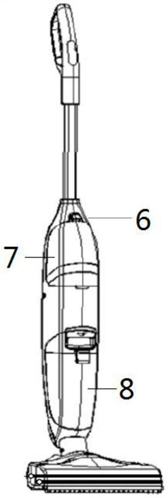
[0033] This embodiment is a kind of cleaning equipment. The cleaning equipment can be a washing machine, a floor washing machine, a window cleaning machine, a scraper, etc., which are assisted by water to clean the equipment, which can realize the cleaning of the ground, carpet, floor, wall, glass, Cleaning operations such as car windows. Such as figure 2 and image 3 shown, including:
[0034] The main body 6 is provided with a clean water tank accommodation area and a sewage tank accommodation area;
[0035] The clean water tank 7 is arranged in the clean water tank accommodation area;
[0036] Specifically, the clean water tank 7 itself is detachably arranged on the main body 6, and a buckle is provided at the position of the clean water tank accommodation area, and the clean water tank 7 itself is connected to the main body 6 through the buckle. The clean water tank 7 is provided with a water injection port and a water outlet. When the water injection operation is req...
Embodiment 2
[0081] This embodiment is made on the basis of Embodiment 1. In this embodiment, the force driving the force transmission part 4 to move may be a pulling force or a pushing force.
[0082] As another embodiment, when the external force is set as pulling force or pushing force, a mechanical arm may be provided on the inner wall of the box body 1 to realize the driving operation of the force transmission part 4 .
[0083] Specifically, there is no limitation on the driving method of the mechanical arm, which may be driven by manual control or automatic control.
[0084] As an implementation, when manual control is adopted, a transmission structure connected to the mechanical arm needs to be provided on the liquid storage device, and the transmission structure can adopt a multi-link structure.
[0085] Specifically, during the cleaning process, the user can detect the water level of the sewage inside the tank 1 by visual observation, and then when the water level of the sewage ex...
Embodiment 3
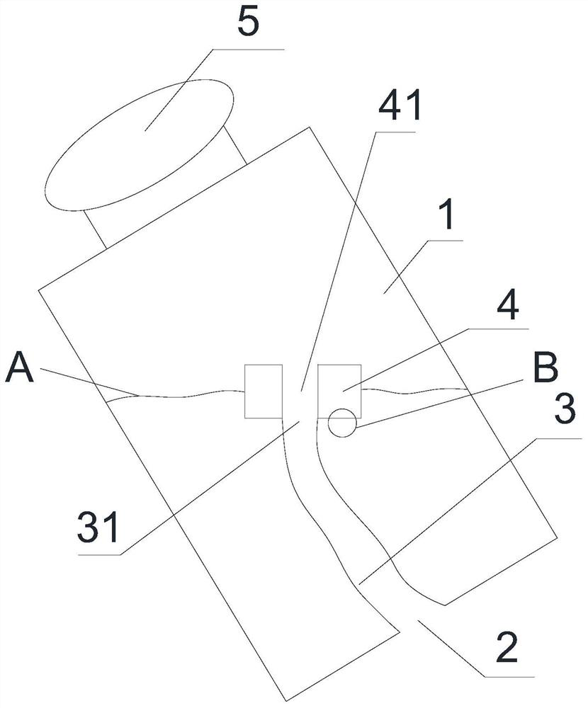
[0093] This embodiment is made on the basis of Embodiment 1. In this embodiment, the force driving the force transmission part 4 to move is magnetic force.
[0094] In this embodiment, a magnetic force generating device is provided on one of the box body 1 or the force transmission part 4, and a liquid level sensor is set on the force transmission part 4 at the same time. When the liquid level inside the box body 1 rises, the liquid level sensor It will control the activation of the magnetic force generating device, so as to drive the force transmission part 4 to move up with the liquid level.
[0095] As an embodiment, the force transmission part 4 itself is made of iron, and the magnetic force generating device is arranged inside the box body 1 . As a modification, the force transmission part 4 may also be made of magnetic steel, magnets and the like.
[0096] As another embodiment, the force transmission part 4 is provided with a magnetic force generating device, and at th...
PUM
 Abstract
Description
Claims
Application Information
 - R&D Engineer
- R&D Manager
- IP Professional
- Industry Leading Data Capabilities
- Powerful AI technology
- Patent DNA Extraction
Browse by: Latest US Patents, China's latest patents, Technical Efficacy Thesaurus, Application Domain, Technology Topic.
© 2024 PatSnap. All rights reserved.Legal|Privacy policy|Modern Slavery Act Transparency Statement|Sitemap