
Supporting iron numerical control integrated forming machine

A forming machine and supporting iron technology, applied in forming tools, metal processing equipment, manufacturing tools, etc., can solve the problems of increased processing costs, wear of equipment parts, frequent wear of punches, etc., to achieve improved quality, improved efficiency, Practical effect

Pending Publication Date: 2021-07-27
湖北伊电缘科技有限公司
View PDF18 Cites 0 Cited by
  • Summary
  • Abstract
  • Description
  • Claims
  • Application Information

AI Technical Summary

Problems solved by technology

In the production and use of power equipment, support iron is required. The current commonly used processing method for support iron is to pre-bend the workpiece first, then fold the angle steel in half, then punch holes, and finally cut the arc to complete one end of the support iron. After the processing, change the other end to repeat the above processing steps. The process is complicated, because the thickness of the workpiece after folding reaches more than 10mm, the punch is frequently worn during punching, the replacement is not very convenient, the efficiency is low, and the wear of the equipment parts is serious. Increased processing costs

Method used


Image

  • Supporting iron numerical control integrated forming machine
  • Supporting iron numerical control integrated forming machine
  • Supporting iron numerical control integrated forming machine

Examples


Embodiment approach

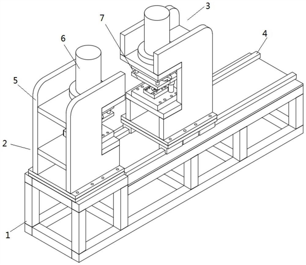
[0022] In an optimized embodiment, the moving direction of the second hydraulic mechanism 3 is toward one side of the composite mold 7 of the first hydraulic mechanism 2 .

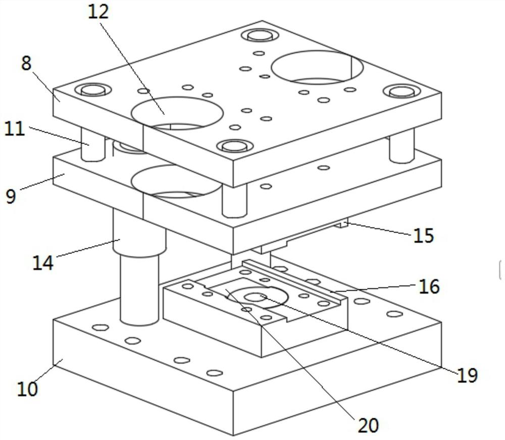
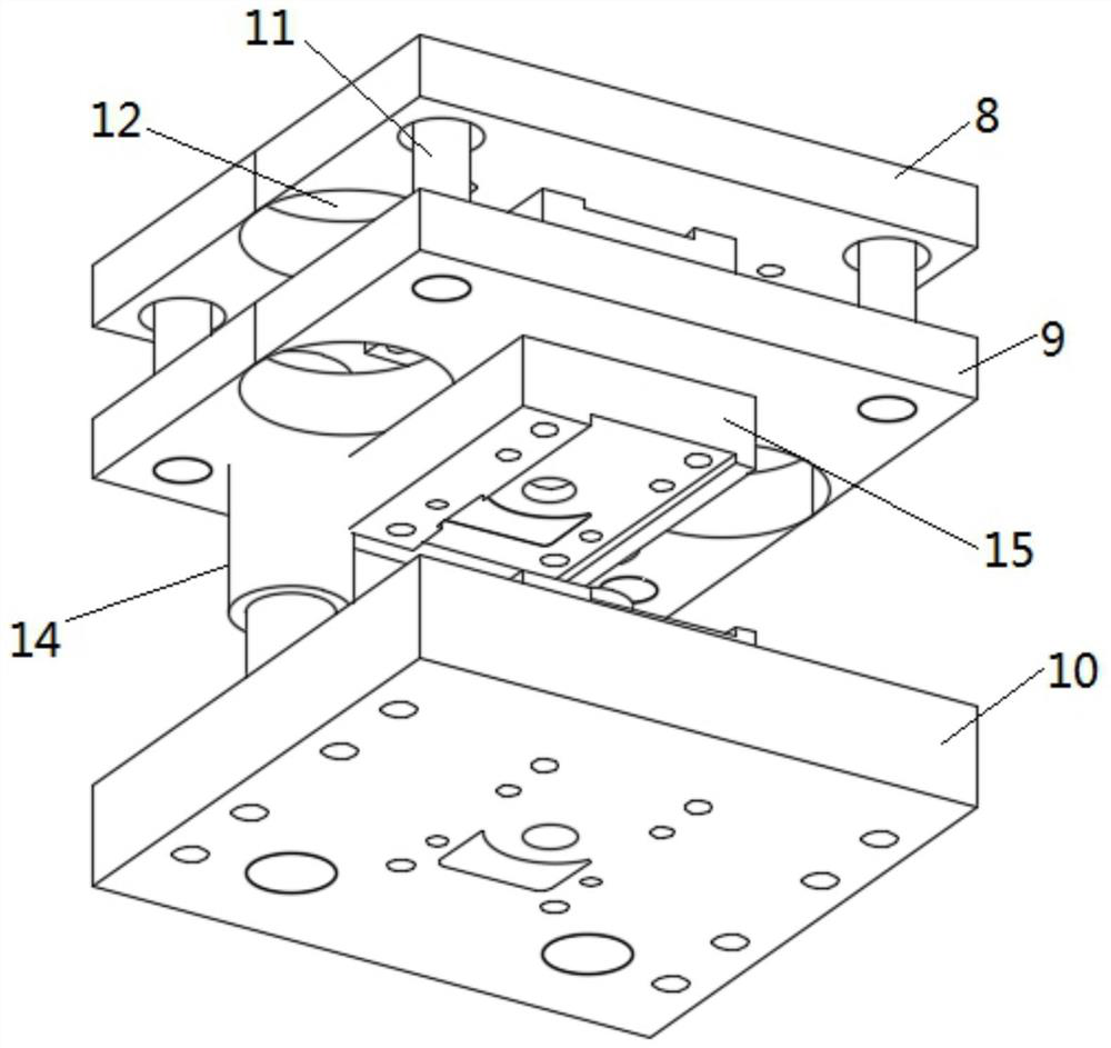
[0023] In an optimized embodiment, the composite mold 7 includes an upper plate 8, a middle plate 9 and a lower plate 10, the lower plate 10 is arranged on the hydraulic main frame 5, the upper plate 8 is connected to the hydraulic cylinder 6, The middle plate 9 is arranged between the upper plate 8 and the lower plate 10, and the four corners of the upper plate 8 and the middle plate 9 are connected with four positioning guide posts 11, and the positioning guide posts 11 passes through the upper plate 8, the upper plate 8 and the lower plate 9 are respectively provided with through holes 12, the through hole 12 of the upper plate 8 and the through hole 12 of the lower plate 9 There is a spring 13 between them. After the hydraulic oil cylinder is started, it will exert pressure on the upper plate. This pre...


PUM


Abstract

The invention relates to a supporting iron numerical control integrated forming machine. The supporting iron numerical control integrated forming machine mainly comprises a rack support, a first hydraulic mechanism and a second hydraulic mechanism; the first hydraulic mechanism and the second hydraulic mechanism are oppositely arranged; the first hydraulic mechanism and the second hydraulic mechanism are the same in structure; the first hydraulic mechanism is fixedly arranged on one side of the rack support; two parallel sliding guide rails are arranged on the other side of the rack support; the second hydraulic mechanism is arranged on the sliding guide rails and can move along the sliding guide rails to adjust the distance between the second hydraulic mechanism and the first hydraulic mechanism; each one of the first hydraulic mechanism and the second hydraulic mechanism comprises a hydraulic main frame, a hydraulic oil cylinder and a composite die; the hydraulic oil cylinder is arranged at the top end of the hydraulic main frame; the composite die is arranged on the hydraulic main frame and located below the hydraulic oil cylinder; the heights of the two composite dies are the same; and the opening ends of the two composite dies are oppositely arranged. The supporting iron numerical control integrated forming machine is high in practicability; machining of workpieces of different sizes can be met; the procedures of bending, punching, arc cutting and the like are fused through the composite die; multiple procedures can be carried out at a time; and higher efficiency is achieved.

Description

technical field [0001] The invention relates to the technical field of support iron forming equipment, in particular to a support iron numerical control integrated forming machine. Background technique [0002] With the continuous development of cities and towns in various regions of the country, there are more and more factors affecting the traffic capacity of urban roads. In order to improve the transportation capacity of cities, cities and regions are constantly building high-speed railways and expressways. In areas, it is necessary to build iron towers for power transmission and overhead high-voltage wires and cables. In the production and use of power equipment, support iron is required. The current commonly used processing method for support iron is to pre-bend the workpiece first, then fold the angle steel in half, then punch holes, and finally cut the arc to complete one end of the support iron. After the processing, change the other end to repeat the above processi...

Claims


Application Information

Patent Timeline
Patent Type & Authority Applications(China)
IPC IPC(8): B21D35/00B21D37/10
CPCB21D35/001B21D35/003B21D37/10
Inventor 阳俊
Owner 湖北伊电缘科技有限公司
Learn More