Permanent magnet material cutting equipment

A technology for cutting equipment and permanent magnet materials, applied in stone processing equipment, stone processing tools, inductance/transformer/magnet manufacturing, etc., can solve problems such as vibration, high temperature, and material loss of magnetism, so as to prevent loss of magnetism and save resources , Prevent the effect of overheating

Active Publication Date: 2021-07-27
东阳市盛邦磁业有限公司
View PDF6 Cites 0 Cited by
  • Summary
  • Abstract
  • Description
  • Claims
  • Application Information

AI Technical Summary

Problems solved by technology

[0002] In the production of permanent magnetic materials, there will always be remodeling of processed materials. Cutting with traditional cutting methods will undoubtedly cause vibration and high temperature. These unfavorable factors will cause the material to lose magnetism. The invention solves the above problems

Method used


Image

  • Permanent magnet material cutting equipment
  • Permanent magnet material cutting equipment
  • Permanent magnet material cutting equipment

Examples


specific Embodiment approach 1

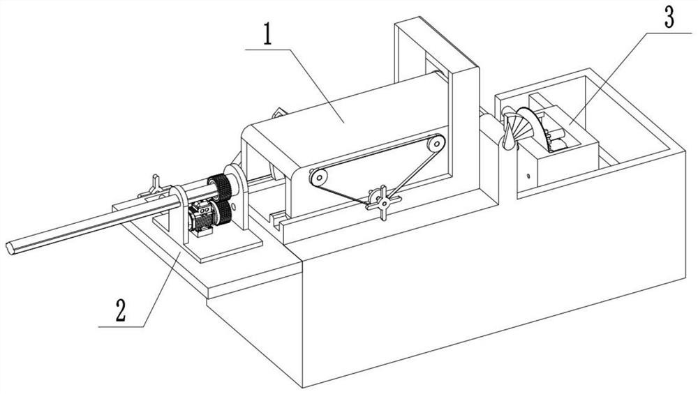
[0028] Combine below Figure 1-12 Describe this embodiment, a permanent magnet material cutting equipment, including a clamping assembly 1, a push-pull assembly 2 and a cutting assembly 3, the push-pull assembly 2, cutting assembly 3 are connected to the clamping assembly 1 .

specific Embodiment approach 2

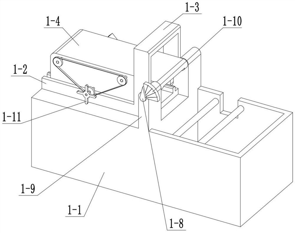
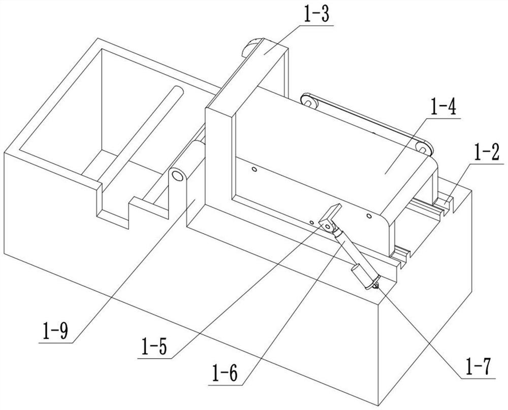
[0030] Combine below Figure 1-12Describe this embodiment, this embodiment will further explain the first embodiment, the clamping assembly 1 includes the equipment shell 1-1, the shockproof bracket I1-2, the shockproof bracket II1-3, the clamp shell 1-4, the electric cylinder support Ear Ⅰ 1-5, electric cylinder 1-6, electric cylinder supporting ear Ⅱ 1-7, turning shaft 1-8, turning supporting lug 1-9, angle plate 1-10, handle Ⅰ 1-11, threaded shaft Ⅰ 1-12, belt Wheel Ⅰ 1-13, belt 1-14, threaded shaft Ⅱ 1-15, fixture Ⅰ 1-16, fixture Ⅰ chute 1-17, fixture Ⅱ 1-18 and fixture Ⅱ slide 1-19, equipment shell 1-1 and shockproof bracket Ⅰ 1 -2 is connected, the anti-vibration support I1-2 is connected with the anti-vibration support II1-3, the equipment shell 1-1 is connected with the flip lug 1-9, the flip lug 1-9 is connected with the angle plate 1-10, and the fixture The shell 1-4 is connected with the turning shaft 1-8, the turning shaft 1-8 is connected with the turning lug 1-9...

specific Embodiment approach 3

[0032] Combine below Figure 1-12 Describe this embodiment, this embodiment will further explain Embodiment 1, the push-pull assembly 2 includes a push-pull bottom plate 2-1, a carriage chute 2-2, a handle II 2-3, a threaded shaft III 2-4, and a carriage 2 -5. Push-pull bracket Ⅰ2-6, push-pull bracket Ⅱ2-7, motor 2-8, gear Ⅰ2-9, gear Ⅱ2-10, threaded sleeve 2-11 and push-pull rod 2-12, push-pull bottom plate 2-1 and equipment The shell 1-1 is connected, the carriage chute 2-2 is located in the push-pull bottom plate 2-1, the carriage 2-5 is slidably connected with the carriage chute 2-2, the handle Ⅱ2-3 is connected with the threaded shaft Ⅲ2-4 , the threaded shaft III2-4 is rotationally connected with the push-pull bottom plate 2-1, the threaded shaft III2-4 is threadedly connected with the slide frame 2-5, the push-pull bracket I2-6, and the push-pull bracket II2-7 are connected with the slide frame 2-5, The motor 2-8 is connected with the carriage 2-5, the motor 2-8 is conn...


PUM


Abstract

The invention relates to the field of novel materials, in particular to permanent magnet material cutting equipment. During production of permanent magnet materials, the materials may be demagnetized by adverse factors such as vibrations and high temperature generated by a conventional cutting way for modification of processed materials. To solve the problems, the permanent magnet materials are put into a clamping assembly; the clamping assembly clamp circular rod materials of different diameters at different angles, so that cutting under various conditions is convenient; vibrations are not generated when the clamping assembly cuts, so that demagnetization is effectively prevented; the assembly can be pushed and pulled to adjust the cutting length, and a cutting assembly can cut the materials at a uniform speed and a low speed, so that vibrations are reduced to be the smallest; and saw blades are cooled by cooling liquid all the time during cutting, and the sprayed-out cooling liquid is re-added into a cooling liquid box after being filtered and cooled to a proper temperature, so that the materials are prevented from being demagnetized due to loss of cooling effect at a high temperature of the cooling liquid while resources are saved.

Description

technical field [0001] The invention relates to a new material field, more specifically a permanent magnet material cutting device. Background technique [0002] In the production of permanent magnetic materials, there will always be remodeling of processed materials. Cutting with traditional cutting methods will undoubtedly produce vibration and high temperature. These unfavorable factors will cause the material to lose magnetism. The present invention solves the above problems. Contents of the invention [0003] The purpose of the present invention is to provide a permanent magnet material cutting equipment, which can. [0004] The purpose of the present invention is achieved through the following technical solutions: [0005] A permanent magnet material cutting device comprises a clamping assembly, a push-pull assembly and a cutting assembly, and the push-pull assembly and the cutting assembly are all connected to the clamping assembly. [0006] As a further optimizat...

Claims


Application Information

Patent Timeline
Patent Type & Authority Applications(China)
IPC IPC(8): B28D1/22B28D7/02B28D7/04H01F41/02
CPCB28D1/22B28D7/02B28D7/04H01F41/0253
Inventor 侯凤玲
Owner 东阳市盛邦磁业有限公司
Why Eureka
Try Eureka