Reinforcing construction method for micro pile of soft soil foundation

A construction method and technology of micro piles, which are applied in soil protection, infrastructure engineering, sheet pile walls, etc., can solve the problems of large slenderness ratio of micro piles, limited bearing capacity of micro piles, uncontrollable grouting direction, etc. The effect of increasing the overall bearing capacity, facilitating penetration and filling, and improving the ability to resist pullout and compressive upper loads

Active Publication Date: 2021-07-27
山东高新岩土科技有限公司
View PDF8 Cites 2 Cited by
  • Summary
  • Abstract
  • Description
  • Claims
  • Application Information

AI Technical Summary

Problems solved by technology

[0003]This application is to solve the problem that the existing micro-pile has a large slender ratio and a small cross-sectional area, and it only relies on the solidified grout to increase the contact with the ground area, thereby increasing the bonding effect with the soil foundation, but when subjected to large external drawing and extrusion forces, the bearing capacity of the micro-pile is still limited. At the same time, due to the softness of the soft soil foundation, the existing grouting method The grouting direction is uncontrollable, and grouting is prone to occur. How to easily control the grouting direction on the basis of enhancing the bearing capacity of the micro-pile, and reduce the waste of grouting caused by grouting. This application designs a method for The reinforcement construction method of micro piles in soft soil foundation, the specific scheme adopted is:

Method used


Image

  • Reinforcing construction method for micro pile of soft soil foundation
  • Reinforcing construction method for micro pile of soft soil foundation
  • Reinforcing construction method for micro pile of soft soil foundation

Examples


Embodiment Construction

[0025] In order to clearly illustrate the technical features of this solution, the present invention will be described in detail below through specific implementation methods and in conjunction with the accompanying drawings.

[0026] In addition, in the description of the present invention, it should be understood that the terms "center", "upper", "lower", "front", "rear", "left", "right", "vertical", "horizontal" ", "Top", "Bottom", "Inner", "Outer", "Axial", "Radial", "Circumferential" and other indicated orientations or positional relationships are based on the orientations or positional relationships shown in the drawings , is only for the convenience of describing the present invention and simplifying the description, but does not indicate or imply that the referred device or element must have a specific orientation, be constructed and operated in a specific orientation, and thus should not be construed as limiting the present invention.

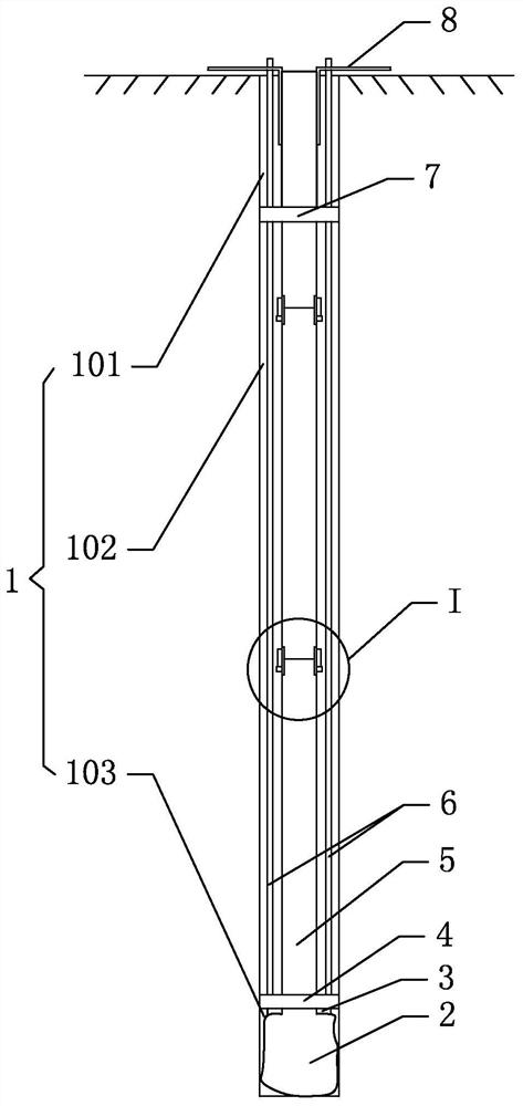
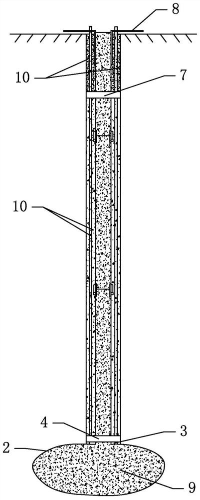
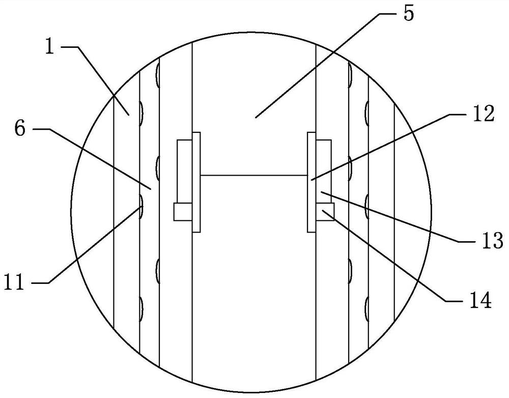
[0027] Such as Figure 1-3 Sho...


PUM


Abstract

The invention relates to a reinforcing construction method of a micro pile for a soft soil foundation, which belongs to the field of micro piles. The reinforcing construction method comprises the following steps that a, a hole is drilled in the foundation; b, a grouting film bag is connected with the bottom end of a main grouting pipe, meanwhile, a first blocking plate is vertically connected with the bottom end of the main grouting pipe, and the first blocking plate is located above the grouting film bag; c, the main grouting pipe with the bottom end connected with the grouting film bag is inserted into the drill hole, then at least two auxiliary grouting pipes are inserted into the drill hole on the outer side of the main grouting pipe, and grout leakage holes are formed in the outer walls of the auxiliary grouting pipes; d, cement grout is injected into the auxiliary grouting pipes, the drill holes in the outer sides of the main grouting pipes are filled with the cement grout, and the cement grout is waited to be solidified; and e, after the cement grout is solidified, cement mortar is injected into the main grouting pipe at high pressure, and the grouting film bag at the bottom is expanded through the cement mortar to form a bag body. The grouting direction can be easily controlled on the basis that the bearing capacity of the micro pile is enhanced, and the problem of waste of the grout amount caused by grout runout is solved.

Description

technical field [0001] The invention relates to the field of micro piles for soil foundations, in particular to a reinforcement construction method for micro piles used for soft soil foundations. Background technique [0002] Micro piles generally refer to cast-in-place piles with a pile diameter less than 400mm and a slenderness ratio greater than 30, which are formed by drilling and inserting steel pipes. Steel pipe micropiles play an important role in soft soil foundation reinforcement engineering and slope anti-slide protection engineering, especially on some soft soil foundations where large machinery cannot enter the site, the role of micropiles is more obvious. At present, the existing soft soil micro-pile is generally carried out by traditional grouting method, that is, the traditional grouting method is to drill a hole in the foundation, then insert a grouting pipe into the hole, and grout outside the grouting pipe first. , and then inject grout into the grouting p...

Claims


Application Information

Patent Timeline
Patent Type & Authority Applications(China)
IPC IPC(8): E02D3/12E02D5/46E02D15/04
CPCE02D3/12E02D5/46E02D15/04Y02A10/23
Inventor 于海洋徐程王正泽杨广亮王嘉栋陈鸿沛于伟伟张洪管张禹良张明祥褚志勇黄强吉王艳华韩帅
Owner 山东高新岩土科技有限公司
Why Eureka
Try Eureka