Cross-shaped steel concrete column stirrup constraint structure and manufacturing method

A cross-shaped steel and concrete column technology, applied in the direction of structural elements, columns, pier columns, etc., can solve the problems of complex construction and low bearing capacity, and achieve the effect of improving bearing capacity, increasing bearing capacity, and reducing the opening ratio

Pending Publication Date: 2021-07-27
NANJING YANGTZE RIVER URBAN AGCHITECTURAL DESIGN
View PDF0 Cites 0 Cited by
  • Summary
  • Abstract
  • Description
  • Claims
  • Application Information

AI Technical Summary

Problems solved by technology

[0004] Therefore, the object of the present invention is to provide a cross-shaped steel concrete column stirrup restraint structure and method, which solves the problem that in the prior art, due to the large cross-sectional size of the column and the presence of steel in the column, the configuration of the stirrup often requires opening holes on the steel to Form an effective restraint on concrete, the construction is more complicated, and the bearing capacity is lower

Method used


Image

  • Cross-shaped steel concrete column stirrup constraint structure and manufacturing method
  • Cross-shaped steel concrete column stirrup constraint structure and manufacturing method
  • Cross-shaped steel concrete column stirrup constraint structure and manufacturing method

Examples


Embodiment 1

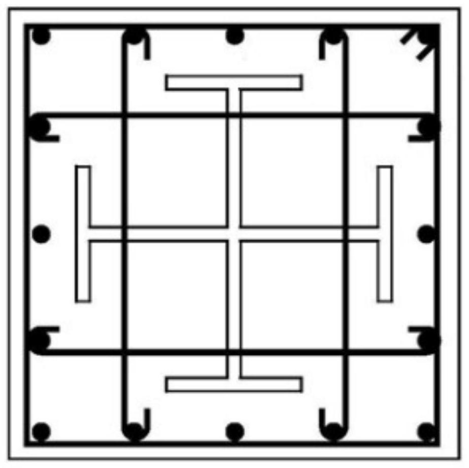
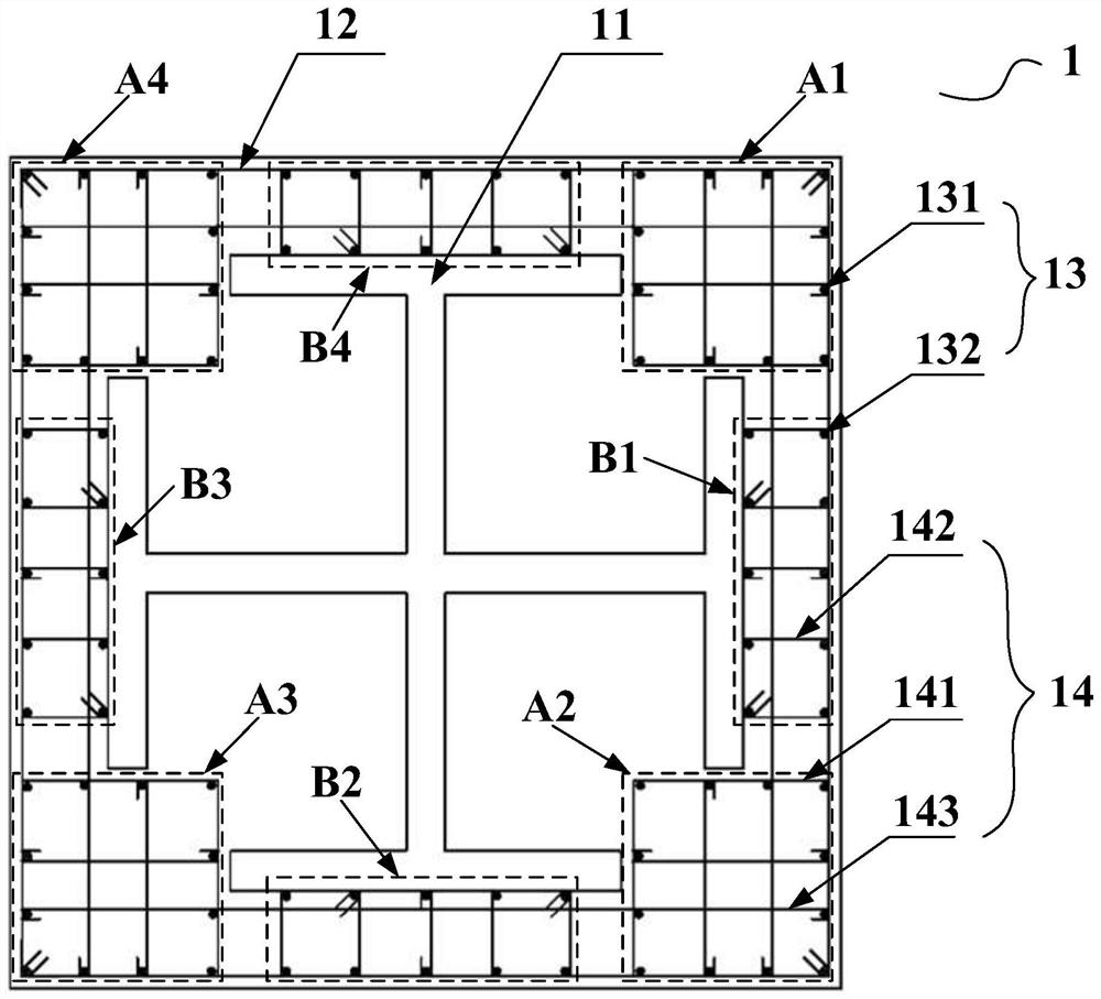
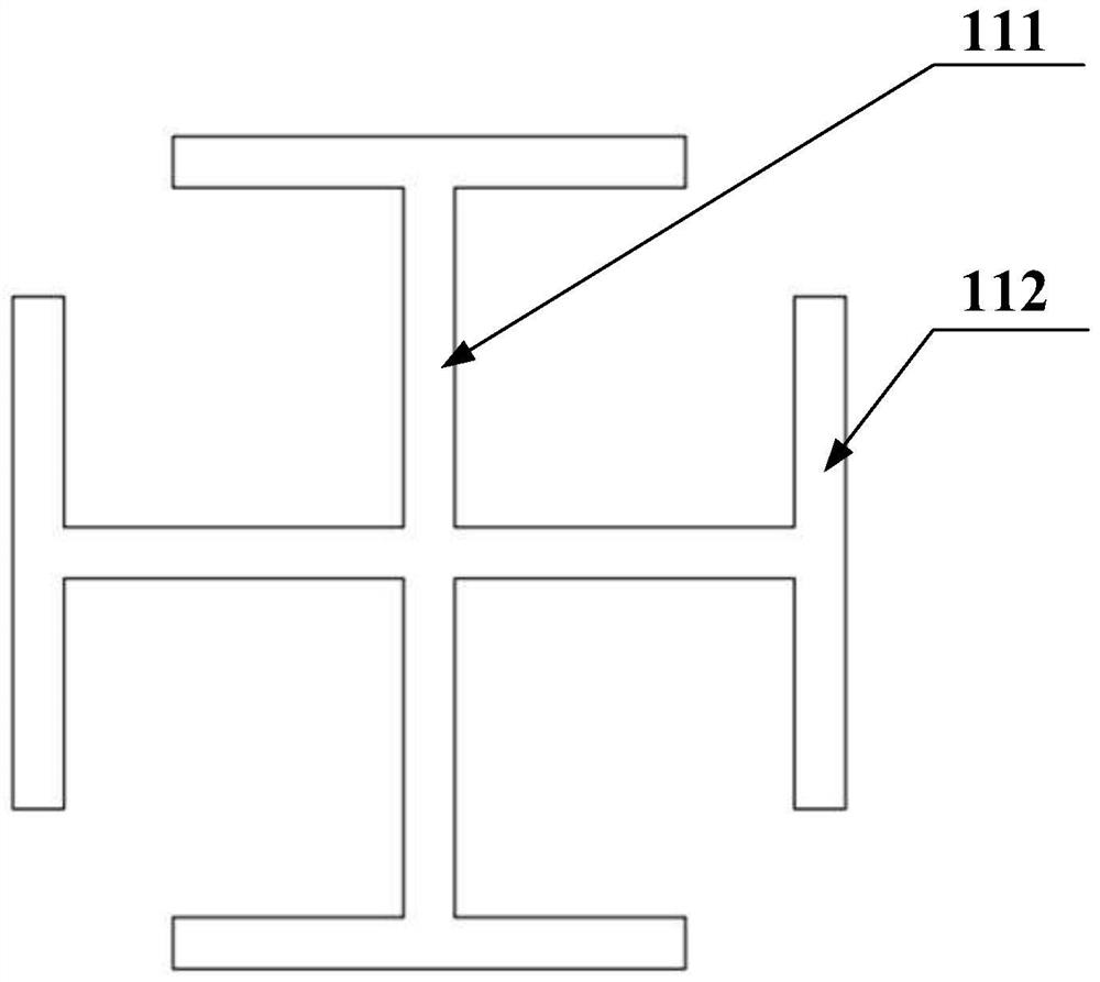
[0038] figure 2 A sectional view of the cross-shaped steel concrete column stirrup restraint structure of the present embodiment is shown; image 3 A plan view of the cross-shaped steel in this embodiment is shown. Such as figure 2 and image 3 As shown, this embodiment proposes a cross-shaped steel concrete column stirrup restraint structure, wherein the cross-shaped steel concrete column 1 includes cross-shaped steel 11, peripheral stirrups 12, longitudinal bars 13 and inner surrounding stirrups 14, wherein,

[0039] The cross-shaped steel 11 is arranged at the center of the cross-shaped steel concrete column 1, the peripheral stirrups 12 are arranged at the periphery of each cross section of the cross-shaped steel concrete column 1, and the longitudinal bars 13 are also arranged at the periphery of the cross-shaped steel concrete column 1 Area, specifically, the longitudinal bars 13 are arranged in the area between the peripheral stirrups 12 and the cross-shaped steel ...

Embodiment 2

[0047] This embodiment proposes a manufacturing method of the cross-shaped steel concrete column stirrup restraint structure in the above-mentioned embodiment 1, comprising the following steps:

[0048] S1. Pouring concrete hollow columns in the concrete rubber mandrel.

[0049] S2. Bind the outer stirrups 12, the longitudinal bars 13, and the inner stirrups 14 constraining the longitudinal bars 13 with nylon cable ties to form a reinforcement cage.

[0050] Specifically, such as image 3 As shown, the cross-shaped steel 11 includes two column webs 111 in an orthogonal crossing and a flange plate 112 arranged at the end of each column web.

[0051] Specifically, such as figure 2 As shown, the longitudinal ribs 13 are divided into four groups of corner longitudinal ribs 131 distributed in a rectangular grid, and four groups of side longitudinal ribs 132 distributed in a rectangle, and the corner restraint stirrups 141 are used to pair the corner longitudinal ribs 131 For bi...


PUM


Abstract

The invention relates to the technical field of building structure design and civil engineering construction, in particular to a cross-shaped steel concrete column stirrup constraint structure and a manufacturing method. The problems that in the prior art, when stirrups are configured, holes need to be formed in profile steel to form an effective constraint effect on concrete, and construction is complex are solved. The cross-shaped steel concrete column comprises cross-shaped steel arranged in the center of the cross-shaped steel concrete column, peripheral stirrups arranged on the peripheries in all cross sections of the cross-shaped steel concrete column, and longitudinal bars arranged between the cross-shaped steel and the peripheral stirrups and extending in the column height direction. Each cross section of the cross-shaped steel concrete column is further internally provided with an internal stirrup for restraining the longitudinal bars. The stirrups do not penetrate through the profile steel, construction is convenient, the aperture ratio of the cross-shaped steel is reduced, and the bearing capacity of the steel reinforced concrete column can be improved.

Description

technical field [0001] The invention relates to the technical field of building structure design and civil construction, in particular to a cross-shaped steel-concrete column stirrup restraint structure and a manufacturing method of the cross-shaped steel-concrete column stirrup restraint structure. Background technique [0002] In super high-rise buildings, in order to improve the rigidity and bearing capacity of the structure, composite structural members are used to ensure the mechanical performance of steel and concrete. Especially when the structure has a high floor height, steel concrete with large cross-section is usually used. Columns, and steel reinforced concrete columns in the case of steel, longitudinal bars, stirrups and even tie bars exist at the same time, the arrangement of cross-sectional reinforcement is particularly complicated. Reasonable arrangement of reinforcement on the section of such members, especially the arrangement of stirrups, is the key to ens...

Claims


Application Information

Patent Timeline
Patent Type & Authority Applications(China)
IPC IPC(8): E04C3/34E04C3/32E04C5/06
CPCE04C3/32E04C3/34E04C5/0609
Inventor 江韩赵学斐
Owner NANJING YANGTZE RIVER URBAN AGCHITECTURAL DESIGN
Why Eureka
Try Eureka