Supercharge Your Innovation With Domain-Expert AI Agents!

Adjustable cavitation venturi tube

A venturi tube and steam adjustment technology, applied in the direction of valve lift, shaft seal, valve details, etc., can solve the problems of poor flow control effect and poor adjustment accuracy, so as to achieve good flow control, precise flow adjustment and good effect Effect

Active Publication Date: 2021-07-27
BEIHANG UNIV
View PDF10 Cites 0 Cited by
  • Summary
  • Abstract
  • Description
  • Claims
  • Application Information

AI Technical Summary

Problems solved by technology

[0004] In order to overcome the deficiencies in the prior art, the application provides an adjustable cavitation venturi to solve the problem of the adjustable cavitation venturi in the prior art. Poor tube adjustment accuracy and poor flow control effect

Method used


Image

  • Adjustable cavitation venturi tube
  • Adjustable cavitation venturi tube
  • Adjustable cavitation venturi tube

Examples


Embodiment 1

[0039] see Figure 1 to Figure 6 , an adjustable cavitation venturi provided in this embodiment, specifically relates to an adjustable cavitation venturi based on the feedback of a differential pressure variable displacement sensor 210, which is applied in the field of rocket engines and used for flow regulation .

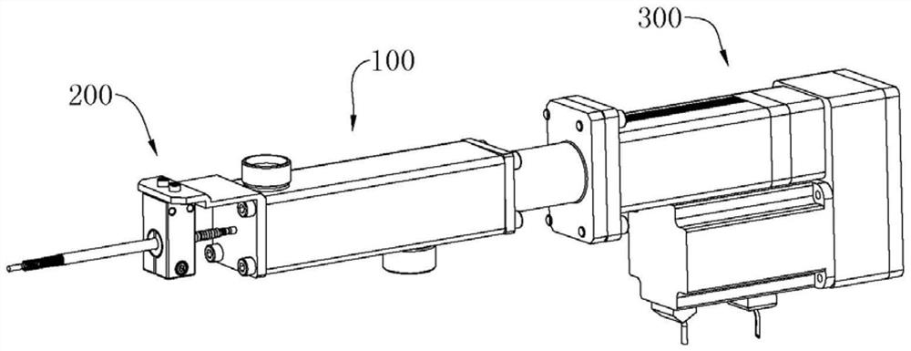
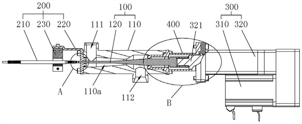
[0040] Please refer to figure 1 and figure 2, The adjustable cavitation venturi provided in this embodiment includes: a venturi adjustment mechanism 100, a displacement detection mechanism 200, a driving mechanism 300 and a controller (not shown in the figure). Wherein, the driving mechanism 300 is arranged at one end of the venturi regulating mechanism 100 , and the driving mechanism 300 is used to drive the venturi regulating mechanism 100 for adjustment, so as to control the flow rate of the venturi regulating mechanism 100 . The displacement detection mechanism 200 is arranged at the other end of the venturi adjustment mechanism 100, and the displacement de...

Embodiment 2

[0063] see figure 1 , figure 2 as well as Figure 4 , an adjustable cavitation venturi provided in this embodiment is applied to flow regulation. This embodiment is an improvement made on the technical basis of the above-mentioned embodiment 1. Compared with the above-mentioned embodiment 1, the difference in:

[0064] The adjustable cavitation venturi provided in this embodiment also includes a limit mechanism 400, which is arranged between the driving mechanism 300 and the venturi body 110, and the limit mechanism 400 is used to limit the axis of the spool 120. to the displacement.

[0065] Specifically, the limit mechanism 400 includes a limit sleeve 400a, the limit sleeve 400a is sleeved on the valve core 120, the limit sleeve 400a is provided with a limit boss 410, and the limit boss 410 and the shoulder on the valve core 120 For touch fit. Optionally, the limiting boss 410 is circular and arranged along the circumference of the inner wall of the limiting sleeve 400...

Embodiment 3

[0071] see figure 2 , Figure 5 as well as Figure 6 , an adjustable cavitation venturi provided in this embodiment is applied to flow regulation. This embodiment is an improvement made on the technical basis of the first or second embodiment above. Or embodiment two, the difference is:

[0072] In this embodiment, the axial section of the throat 114 is trapezoidal, preferably isosceles trapezoidal. That is to say, the shape of the throat 114 is a truncated circular cavity. The spool 120 is provided with a cone section 121 corresponding to the position of the throat 114, wherein the outer wall surface of the cone section 121 is parallel to the inner wall surface of the throat 114, so that the minimum flow section of the throat 114 of the venturi body 110 is no longer is a specific section. That is to say, after the outer wall surface of the cone section 121 is parallel to the inner wall surface of the throat 114, a series of equal-area flow cross-sections are formed in t...


PUM


Abstract

The invention provides an adjustable cavitation venturi tube, and relates to the technical field of flow adjusting equipment. The adjustable cavitation venturi tube comprises a venturi tube adjusting mechanism, a differential variable-pressure displacement sensor, a driving mechanism and a controller; the venturi tube adjusting mechanism comprises a venturi tube body and a valve element, a fluid channel is formed in the venturi tube body in the axial direction, and the valve element is arranged in the fluid channel in a penetrating mode; the differential variable-pressure displacement sensor is arranged at one end of the venturi tube body, and the sensing end of the differential variable-pressure displacement sensor abuts against the valve element; the driving mechanism is arranged at the end, away from the differential variable-pressure displacement sensor, of the venturi tube body and used for driving the valve element to move in the axial direction; and the controller is connected with the differential variable-pressure displacement sensor and the driving mechanism to form closed-loop control, and the controller obtains displacement information of the valve element in real time through the differential variable-pressure displacement sensor and controls the driving mechanism to drive the valve element to move towards a target position according to the displacement information. The displacement and positioning precision of the valve element is high, flow adjustment is accurate, and the flow control effect is good.

Description

technical field [0001] The invention relates to the technical field of flow regulating equipment, in particular to an adjustable cavitation venturi. Background technique [0002] The general adjustable cavitation venturi adjusts the area of ​​the flow cross-section at the throat of the venturi through the movement of the valve stem, so as to achieve the purpose of adjusting the flow rate. [0003] Due to the error in the connection and power transmission between the transmission mechanisms that drive the valve stem to move, when the power is transmitted to the valve stem, the error accumulates to the maximum, which leads to poor adjustment accuracy and poor flow control effect of the adjustable cavitation venturi. . Contents of the invention [0004] In order to overcome the deficiencies in the prior art, the present application provides an adjustable cavitation venturi, which is used to solve the problems of poor adjustment accuracy and poor flow control effect of the ad...

Claims


Application Information

Patent Timeline
Patent Type & Authority Applications(China)
IPC IPC(8): F16K1/02F16K1/36F16K1/32F16K27/02F16K31/04F16K37/00F16K41/02
CPCF16K1/02F16K1/36F16K1/32F16K27/02F16K31/04F16K37/0041F16K41/02
Inventor 田辉张源俊谭广郭子豪王中烁
Owner BEIHANG UNIV
Features
  • R&D
  • Intellectual Property
  • Life Sciences
  • Materials
  • Tech Scout
  • Unparalleled Data Quality
  • Higher Quality Content
  • 60% Fewer Hallucinations
Learn More