Check patentability & draft patents in minutes with Patsnap Eureka AI!

Paper cutting mechanism of high-speed printer

A technology for printers and paper cutting, applied in printing devices, printing, metal processing, etc., can solve problems such as easy generation of burrs, paper scraps, difficult maintenance, frequent replacement, etc., achieve uniform use of cutting edges, simple and ingenious structure, and easy maintenance low difficulty effect

Pending Publication Date: 2021-07-30
苏州天陆图文科技有限公司
View PDF0 Cites 0 Cited by
  • Summary
  • Abstract
  • Description
  • Claims
  • Application Information

AI Technical Summary

Problems solved by technology

[0003] 1. It takes a long time to draw from one side of the paper to the other side, and the efficiency is low;
[0004] 2. When cutting the paper, the edge of the cutting knife and the paper incision are under a large force, it is easy to cut obliquely, and it is also easy to produce burrs, paper scraps, etc., and the paper cutting effect is poor;
[0005] 3. The edge of the scribing knife wears quickly, making the scribing knife easy to damage, short in life, and frequently replaced, making the high-speed printer’s utilization rate low;
[0006] 4. There are fluctuations in the force at the paper incision, which may easily cause the paper to move slightly, resulting in poor printing effect;
[0007] 5. Since the scribing knife needs to slide from one side of the paper to the other, the structure of the paper cutting mechanism is complicated and difficult to maintain

Method used


Image

  • Paper cutting mechanism of high-speed printer
  • Paper cutting mechanism of high-speed printer
  • Paper cutting mechanism of high-speed printer

Examples


Embodiment Construction

[0033] The preferred embodiments of the present invention will be described in detail below in conjunction with the accompanying drawings, so that the advantages and features of the present invention can be more easily understood by those skilled in the art, so as to define the protection scope of the present invention more clearly.

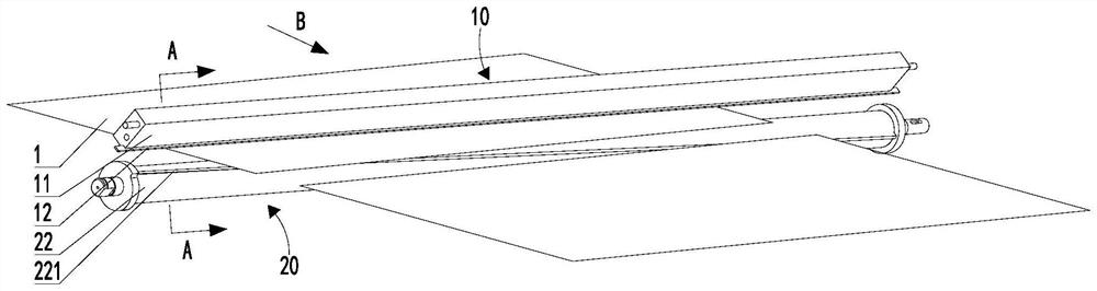
[0034] The traveling direction of paper in the present invention is image 3 The direction indicated by the arrow at B.

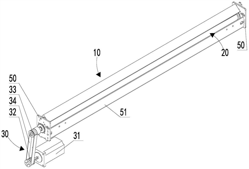
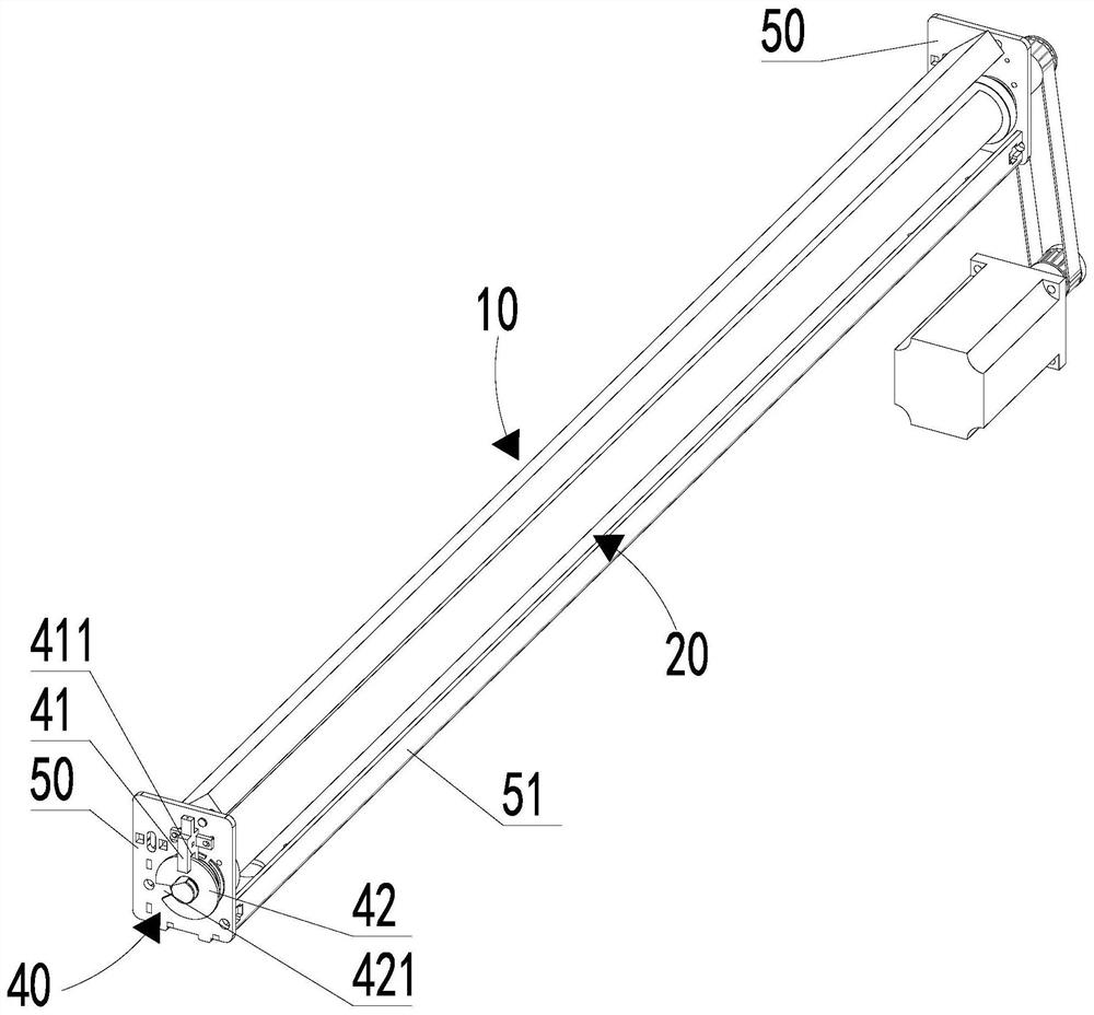
[0035] Such as Figure 1-5 As shown, the paper cutting mechanism of the high-speed printer provided by the present invention includes a cutter, a drive assembly 30, a detection assembly 40 and a fixing assembly, wherein the cutter is used to cut the paper 1, and the cutter includes an upper knife assembly 10 and a lower knife Assembly 20, the upper knife assembly 10 includes an upper knife seat 11 and an upper knife 12, the upper knife seat 11 is a flat part, the extension direction of the upper knife seat 11 is perpendicular...


PUM

PropertyMeasurementUnit
Rotation angleaaaaaaaaaa

Abstract

The invention provides a paper cutting mechanism of a high-speed printer. A lower cutter is spirally wound on the outer circumferential face of a lower cutter holder, the spiral winding rotation angle of the lower cutter is smaller than 180 degrees, an upper cutter holder is rotationally arranged, and elastic pieces used for pulling the upper cutter holder back to the initial position are arranged, so that when the lower cutter holder rotates, an upper cutting edge and a lower cutting edge are cyclically switched between disengagement and point contact, so that it is ensured that paper is cut off when the upper cutting edge and the lower cutting edge are in point contact, impact force applied to the upper cutter by the lower cutter can be reduced through slight rotation of the upper cutter holder, force applied to the cutting edges and a paper notch is reduced, the paper is not prone to being cut obliquely, and burrs, paper scraps and other phenomena can be avoided. The paper cutting effect is good, the stress at the paper notch is more uniform, the fluctuation is small, the paper is more stable during paper cutting, the printing effect is good, the cutting edges are uniform in use, not easy to damage, long in service life, free of frequent replacement, high in utilization rate, simple and ingenious in structure, small in maintenance difficulty, short in consumed time and high in efficiency.

Description

technical field [0001] The invention relates to the field of high-speed printers, in particular to a paper cutting mechanism of a high-speed printer. Background technique [0002] With the rapid development of the printing industry, high-speed printers with fast printing speed and high printing efficiency have gradually become mainstream products. When printing drawings, especially engineering drawings, it is necessary to cut the printed drawings from the paper tape for subsequent reference and review. Binding, the paper cutting mechanism of existing high-speed printers mostly adopts the mode of scratching the paper, which has the following problems at least: [0003] 1. It takes a long time to draw from one side of the paper to the other side, and the efficiency is low; [0004] 2. When cutting the paper, the edge of the cutting knife and the paper incision are under a large force, it is easy to cut obliquely, and it is also easy to produce burrs, paper scraps, etc., and t...

Claims


Application Information

Patent Timeline
IPC IPC(8): B26D1/36B26D7/26B26D5/08B26D7/00B41J11/66
CPCB26D1/36B26D5/086B26D7/00B26D7/2614B41J11/66
Inventor 王小明
Owner 苏州天陆图文科技有限公司
Features
  • R&D
  • Intellectual Property
  • Life Sciences
  • Materials
  • Tech Scout
  • Unparalleled Data Quality
  • Higher Quality Content
  • 60% Fewer Hallucinations
Learn More