Connecting and disconnecting device and disconnecting method for deep sea escape cabin

A technology of release device and escape cabin, which is applied in the field of deep-sea release equipment, can solve the problems that the flange of the locking ring cannot just match the groove of the fence, the escape cabin cannot be released and separated, and the driving mode is single, so as to improve the reliability of release and improve Unlock reliability, avoid stuck effects

Active Publication Date: 2021-07-30
CHINA SHIP SCIENTIFIC RESEARCH CENTER (THE 702 INSTITUTE OF CHINA SHIPBUILDING INDUSTRY CORPORATION)
View PDF0 Cites 6 Cited by
  • Summary
  • Abstract
  • Description
  • Claims
  • Application Information

AI Technical Summary

Problems solved by technology

[0005] 1. The unlocking method (the jack cylinder pushes the locking ring to unlock) and its driving method are single, and the reliability is lacking;
[0006] 2. During the process of rotating and unlocking, the locking ring may drive the escape pod to rotate together, which will cause the flange of the locking ring to fail to match the groove of the fence, making the escape pod unable to be released and separated, and there are design defects;
[0007] 3. Both the pushing device and the unlocking device are driven by the hydraulic system, the driving method is single, and the reliability is lacking
In summary, the existing escape cabin connection release device has certain defects and low reliability

Method used


Image

  • Connecting and disconnecting device and disconnecting method for deep sea escape cabin
  • Connecting and disconnecting device and disconnecting method for deep sea escape cabin
  • Connecting and disconnecting device and disconnecting method for deep sea escape cabin

Examples


Embodiment Construction

[0053] The specific implementation manner of the present invention will be described below in conjunction with the accompanying drawings.

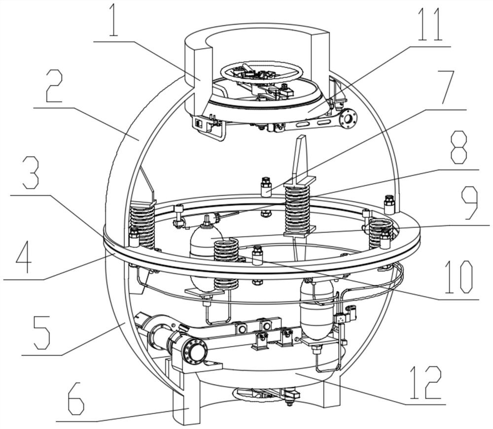
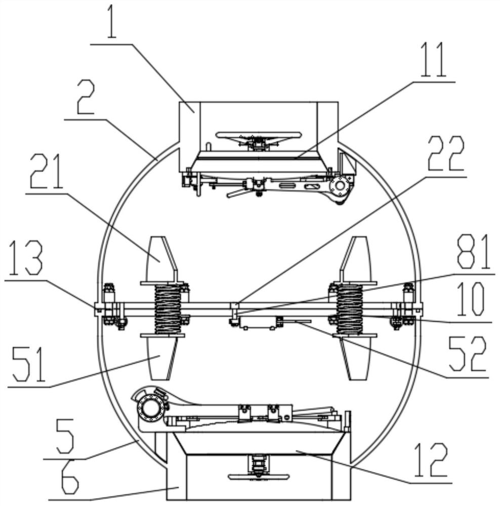
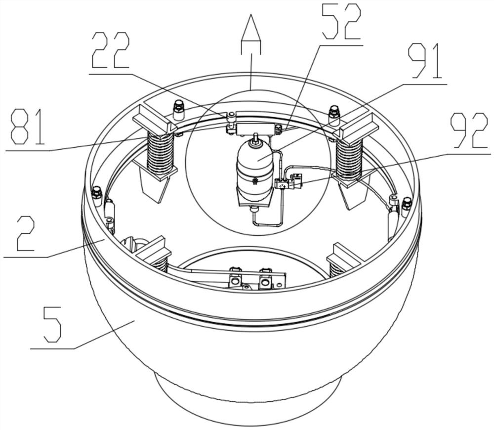
[0054] Such as Figure 1-Figure 9 As shown, the connection and release device for the deep-sea escape cabin of this embodiment includes an upper well 2 and a lower well 5 all in a hemispherical structure. The top of the upper well 2 is provided with an upper passage wall 1, and the upper passage The enclosure wall 1 is connected to the manned ball of the escape cabin, the bottom of the upper enclosure 2 is provided with an upper docking flange 3; the top of the lower enclosure 5 is provided with a lower docking flange 4, and the bottom of the lower enclosure 5 is provided with a lower passage enclosure wall 6. The lower passage wall 6 is connected to the manned cabin of the deep-sea manned submersible;

[0055] The upper butt flange 3 and the lower butt flange 4 are fixedly connected by explosive bolts 7, and the flange surface is sealed by...


PUM

PropertyMeasurementUnit
Wedge angleaaaaaaaaaa

Abstract

The invention discloses a connecting and disconnecting device. The device comprises an upper trunk trap and a lower trunk trap which are both of a hemispherical structure, an upper channel enclosure bulkhead is arranged at the top of the upper trunk trap, the upper channel enclosure bulkhead is connected with an escape cabin manned ball, and an upper butt joint flange is arranged at the bottom of the upper trunk trap; the top of the lower trunk trap is provided with a lower butt flange, the bottom of the lower trunk trap is provided with a lower channel enclosure bulkhead, and the lower channel enclosure bulkhead is connected with a manned cabin of the deep sea manned submersible vehicle; the upper butt joint flange and the lower butt joint flange are fixedly connected through explosive bolts, and flange faces are sealed through sealing rings. An upper hatch cover is installed in the upper channel enclosure bulkhead, a lower hatch cover is installed in the lower channel enclosure bulkhead, and a normal-pressure cavity is formed between the upper trunk trap and the lower trunk trap under the normal working condition. An oil cylinder upper support is installed on the inner side of the lower portion of the upper trunk, a rotary actuating oil cylinder is installed on the oil cylinder upper support through an oil cylinder connecting pin shaft, and an oil cylinder lower support is hinged to the end of the rotary actuating oil cylinder. The working is reliable, and the use is flexible.

Description

technical field [0001] The invention relates to the technical field of deep-sea escape equipment, in particular to a connection and release device and release method for a deep-sea escape cabin. Background technique [0002] Deep-sea manned equipment needs to escape the personnel passage between the cabins underwater, especially after an accident, the accident personnel will enter a specific cabin (emergency escape cabin) through the personnel passage, and the collective escape of personnel can be realized after the escape passage. Emergency escape chambers are often equipped on manned submersibles (or submarines). In an emergency, the crew abandons the boat and enters the escape chamber. After being released, they float to the surface of the water by their own buoyancy and wait for rescue. The escape chamber is usually the last place for the crew to rescue themselves. A guarantee. [0003] In the prior art, it relates to a connection release device for an escape cabin. The...

Claims


Application Information

Patent Timeline
IPC IPC(8): B63G8/41
CPCB63G8/41
Inventor 吴宪王博周鑫涛徐蒙赵远辉
Owner CHINA SHIP SCIENTIFIC RESEARCH CENTER (THE 702 INSTITUTE OF CHINA SHIPBUILDING INDUSTRY CORPORATION)
Why Eureka
Try Eureka