Active control wing plate device for improving wind-induced vibration performance of large-span suspension bridge and suspension bridge

A technology for active control and suspension bridges, applied in the direction of suspension bridges, bridges, bridge forms, etc., can solve the problems of increasing economic costs of use and maintenance, increasing economic costs, and complex structure of active control systems

Pending Publication Date: 2021-07-30
TONGJI UNIV
View PDF6 Cites 0 Cited by
  • Summary
  • Abstract
  • Description
  • Claims
  • Application Information

AI Technical Summary

Problems solved by technology

[0003] The structure of the general active control system is complicated. When it is installed on both sides of the bridge, it will increase the lateral width of the bridge or occupy the space of the bridge deck; at the same time, it will also change the aerodynamic shape of the original bridge. Experimental studies are carried out to ensure that, therefore, the installation of active control systems on both sides of the built bridge will greatly increase the economic cost
On the other hand, the need for external energy supply is also a major drawback of active control measures. Additional energy supply not only needs to increase the power supply line, but also increases the economic cost of use and maintenance.

Method used


Image

  • Active control wing plate device for improving wind-induced vibration performance of large-span suspension bridge and suspension bridge
  • Active control wing plate device for improving wind-induced vibration performance of large-span suspension bridge and suspension bridge
  • Active control wing plate device for improving wind-induced vibration performance of large-span suspension bridge and suspension bridge

Examples


Embodiment Construction

[0028] In order to enable those skilled in the art to better understand the technical solutions in the present invention, the technical solutions in the embodiments of the present invention will be clearly and completely described below in conjunction with the drawings in the embodiments of the present invention. Obviously, the described The embodiments are only some of the embodiments of the present invention, not all of them. Based on the embodiments of the present invention, all other embodiments obtained by persons of ordinary skill in the art without making creative efforts shall fall within the protection scope of the present invention.

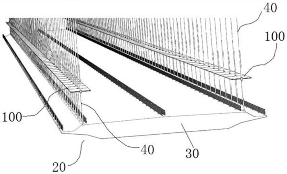
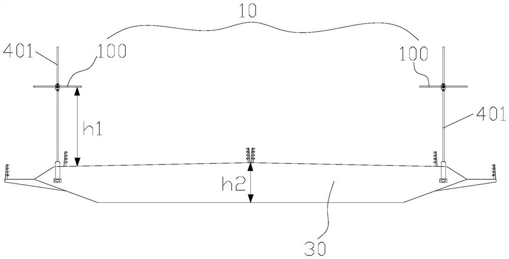
[0029] The embodiment of the present application provides a wing plate device 10 for a long-span suspension bridge 20 . Figure 1-Figure 2 Shown is a suspension bridge 20 using the flap device 10 provided by this embodiment. This application takes the application of the wing plate device 10 to the suspension bridge 20 as an example to ...


PUM


Abstract

The invention discloses an active control wing plate device for improving the wind-induced vibration performance of a large-span suspension bridge and the suspension bridge. The suspension bridge comprises a main beam and a suspender device installed on the main beam, the suspender device comprises two suspender assemblies oppositely arranged in the transverse bridge direction, each suspender assembly comprises a plurality of suspenders arranged at intervals in the longitudinal bridge direction, the wing plate device comprises two wing plate assemblies oppositely arranged in the transverse bridge direction, each wing plate assembly comprises a plurality of wing plates arranged at intervals in the longitudinal bridge direction, each wing plate is installed between every two adjacent suspenders, a driving mechanism is installed on one of every two adjacent suspenders, one end of each wing plate is rotationally connected with the driving mechanism, and the other end of the wing plate rotates relative to the other suspender. The wing plate device provided by the invention is mounted on the suspension bridge suspenders, does not occupy the bridge floor space, has no pneumatic interference on the main beam, achieves the purpose of suppressing the wind-induced vibration of the suspension bridge, does not need to provide additional energy, and reduces the use and maintenance cost.

Description

technical field [0001] The invention relates to the technical field of bridge wind vibration control, in particular to an active control wing plate device and a suspension bridge for improving the wind vibration performance of a long-span suspension bridge. Background technique [0002] Traditional aerodynamic control technology has played an important role in improving the aerodynamic performance of long-span cable-bearing bridges, but various traditional wind-induced vibration control measures are not robust to complex incoming flows and universal in controlling various wind-induced vibrations. The active control technology is to drive the peripheral components of the bridge structure to move through the external input energy, thereby changing the flow pattern around the main girder, improving the aerodynamic force distribution on the surface of the structure, and effectively suppressing the wind-induced vibration of the main girder. The vibration suppression idea of ​​act...

Claims


Application Information

Patent Timeline
IPC IPC(8): E01D11/02E01D19/00H02S20/22F24S20/60
CPCE01D11/02E01D19/00H02S20/22F24S20/60Y02E10/40Y02E10/50Y02B10/10
Inventor 方根深王子龙赵林李珂葛耀君
Owner TONGJI UNIV
Why Eureka
Try Eureka