Vacuum glass heat insulation performance testing device and method

A vacuum glass and testing device technology, applied to measuring devices, using sound waves/ultrasonic waves/infrasonic waves for material analysis, using sound waves/ultrasonic waves/infrasonic waves to analyze solids, etc., can solve problems such as low detection efficiency, strictness, and long time

Pending Publication Date: 2021-07-30
青岛中腾志远真空玻璃科技发展有限公司
View PDF0 Cites 0 Cited by
  • Summary
  • Abstract
  • Description
  • Claims
  • Application Information

AI Technical Summary

Problems solved by technology

[0004] The existing vacuum glass heat insulation performance test method mainly uses the heat preservation detection method. This heat preservation detection method has strict requirements on the external environmental conditions, and the detection time of each piece needs about 30 minutes, which is relatively long and the detection efficiency is too low.

Method used


Image

  • Vacuum glass heat insulation performance testing device and method

Examples


Embodiment 1

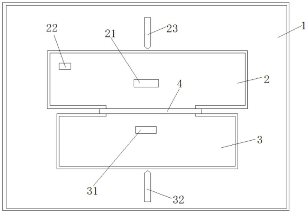
[0026] like figure 1 Shown is the vacuum glass heat insulation performance testing device according to the present invention, including a control system, a quiet room 1, and a sounding box 2 and a receiving box 3 arranged in the quiet room 1. A sounding device 21 and a receiving box 3 are arranged in the sounding box 2 The sound receiver I22 is provided with the sound receiver II31 in the sound receiver 3 .

[0027] The speaker and the receiving speaker are set opposite to each other and placed parallel to the ground. There are openings on the two side walls opposite the emitting and receiving speaker. The sound generator, sound receiver II and the opening are on the same line. Between the opening of the sound box and the sound box; it also includes a sound box pushing mechanism 23 and a sound box pushing mechanism 32, the sound box can move forward and backward under the action of the sound box pushing mechanism, and the sound box can move forward and backward under the effec...

Embodiment 2

[0042] The difference between this embodiment and Embodiment 1 is that the sounding box and the receiving sound box are placed vertically up and down, the sounding box is fixed on the ground of the silent room, and the receiving sound box is fixed directly above the sounding box, and the sounding box can be moved under the action of the sound box pushing mechanism. Moving up and down, the affected speaker can move up and down under the action of the pushing mechanism of the affected speaker.

Embodiment 3

[0044] The difference between this embodiment and Embodiment 1 is that the sound emitting box and the receiving sound box are placed vertically up and down, the receiving sound box is fixed on the ground of the silent room, the sound emitting box is fixed directly above the receiving sound box, and the sound emitting box can be moved under the action of the sound box pushing mechanism. Moving up and down, the affected speaker can move up and down under the action of the pushing mechanism of the affected speaker.


PUM

PropertyMeasurementUnit
barrier rateaaaaaaaaaa

Abstract

The invention relates to the field of vacuum glass detection, and discloses a vacuum glass heat insulation performance testing device and method, the testing device comprises a control system, a mute room, and a sound emitting box and a sound receiving box which are arranged in the mute room, the sound emitting box is internally provided with a sound generator and a sound receiver I, and the sound receiving box is internally provided with a sound receiver II; the sound emitting box and the sound receiving box are oppositely arranged, openings are formed in the two opposite side walls of the sound emitting box and the sound receiving box, the sound generator, the sound receiver II and the openings are located on the same straight line, and vacuum glass is placed between the openings of the sound emitting box and the sound receiving box; the testing device also comprises a sound emitting box pushing mechnaism and a sound receiving box pushing mechanism; the sound generator, the sound receiver I, the sound receiver II, the sound emitting box pushing mechanism and the sound receiving box pushing mechanism are electrically connected with the control system. Compared with the prior art, when the vacuum glass is detected through the testing device, the requirement for the external environment is low, the detection time is short, and the detection efficiency is greatly improved.

Description

technical field [0001] The invention relates to the field of vacuum glass detection, in particular to a vacuum glass heat insulation performance testing device and testing method. Background technique [0002] Vacuum glass is a new type of glass deep-processing product, which is developed based on the principle of vacuum flask. Vacuum glass has excellent heat insulation performance and good heat insulation and noise reduction performance, and has been widely used at home and abroad. [0003] As a thermal insulation material, vacuum glass requires the air pressure in the vacuum compartment to be less than 0.1 Pa, that is, to be below one millionth of an atmosphere. ), the heat conduction and convective heat transfer of the gas can be negligible, so as to achieve the same heat preservation effect as a vacuum flask. If the air pressure in the interlayer is too high, that is, the vacuum degree is poor, the heat transfer caused by the gas will be large, and the thermal insulati...

Claims


Application Information

Patent Timeline
Patent Type & Authority Applications(China)
IPC IPC(8): G01N29/032G01N29/11
CPCG01N29/032G01N29/11G01N2291/015
Inventor 滕少波
Owner 青岛中腾志远真空玻璃科技发展有限公司
Why Eureka
Try Eureka