A polarization-insensitive directional coupler structure and method
A directional coupler, polarization insensitive technology, applied in the coupling of optical waveguides, instruments, optics, etc., can solve the problems of birefringence, polarization insensitivity, etc., achieve easy implementation, less stringent process requirements, and achieve broadband transmission characteristics Effect
- Summary
- Abstract
- Description
- Claims
- Application Information
AI Technical Summary
Problems solved by technology
Method used
Image
Examples
Embodiment 1
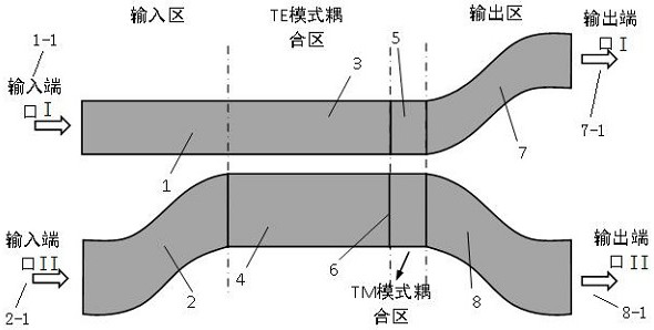
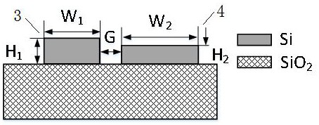
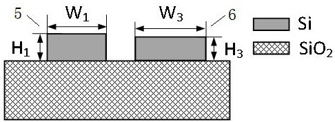
[0051] The structure of a polarization-insensitive directional coupler is as follows figure 1 shown. The cross-sectional structure of the waveguide structure in the TE mode coupling region and the TM mode coupling region is as follows: figure 2 with image 3 shown. Both the TE mode coupling region and the TM mode coupling region are asymmetric directional coupler structures. Among them, the width and height of the coupling waveguide I 3 in the TE mode coupling region are W1=400nm, H1=220nm, the width and height of the coupling waveguide II 4 are W2=575nm, H2=159.3nm, and the coupling gap G=200nm. The width and height of the coupling waveguide III 5 in the TM mode coupling region are W1=400nm, H1=220nm, the height of the coupling waveguide IV 6 is H3=202.5nm, the width W3=575nm, and the coupling gap G=200nm. The length of the curved waveguide in the output region along the beam propagation direction is 30 μm.
[0052] First, we simulate the directional coupler structure i...
PUM
 Abstract
Description
Claims
Application Information
 - R&D
- Intellectual Property
- Life Sciences
- Materials
- Tech Scout
- Unparalleled Data Quality
- Higher Quality Content
- 60% Fewer Hallucinations
Browse by: Latest US Patents, China's latest patents, Technical Efficacy Thesaurus, Application Domain, Technology Topic, Popular Technical Reports.
© 2025 PatSnap. All rights reserved.Legal|Privacy policy|Modern Slavery Act Transparency Statement|Sitemap|About US| Contact US: help@patsnap.com


