
Electric connector

An electrical connector and electrical technology, applied in the direction of connection, parts and circuits of connecting devices, etc., can solve the problems of affecting the shielding effect of the shielding shell, affecting the terminal, affecting the noise level of the terminal interference, etc.

Active Publication Date: 2021-07-30
中山得意电子有限公司
View PDF5 Cites 0 Cited by
  • Summary
  • Abstract
  • Description
  • Claims
  • Application Information

AI Technical Summary

Problems solved by technology

[0003] The debugging of various indicators is mutually restrained and affected. For example, in order to achieve the required characteristic impedance of the terminal, it is necessary to adjust the cross-sectional size of the terminal, the distance between the terminal and the shielding shell, etc., and the cross-sectional size of the terminal also affects The interference attacks emitted by the terminals and the high-current transmission performance of the terminals. Among them, the larger the cross-section of the terminal, the smaller the terminal impedance, and the easier it is to realize the high-current transmission of the terminal, but the easier it is for the terminal to transmit more interference attacks to the outside world , affecting other terminals; the distance between the terminal and the shielding shell affects the shielding effect of the shielding shell, which in turn affects the amount of interference noise received by the terminal

Method used


Image

  • Electric connector
  • Electric connector
  • Electric connector

Examples


Embodiment Construction

[0037] In order to facilitate a better understanding of the purpose, structure, features, and effects of the present invention, the present invention will now be further described in conjunction with the accompanying drawings and specific embodiments.

[0038] In order to make it easier to understand the technical solution of the present invention, the X-axis in the three-dimensional coordinate axes in the accompanying drawings is defined as the first direction, the Z-axis is defined as the second direction, the Y-axis is defined as the third direction, and the X-axis, Y-axis and Two pairs of Z axes are perpendicular to each other.

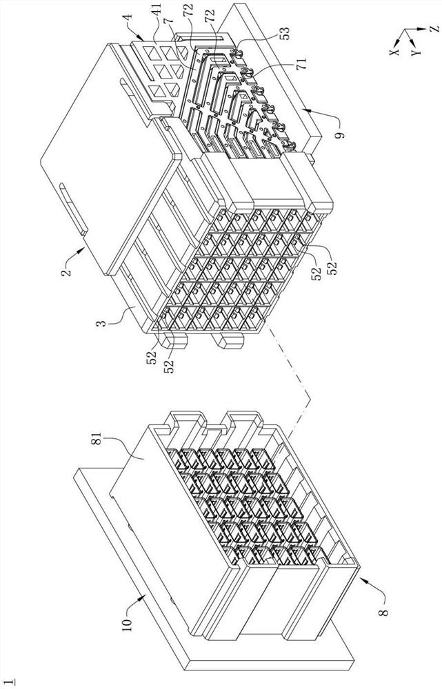
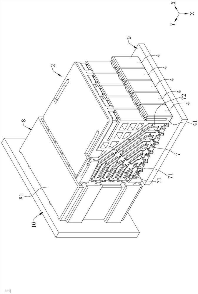
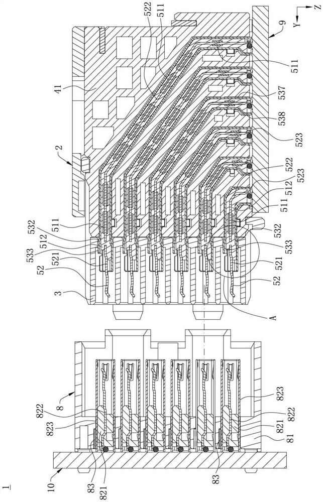
[0039] see Figure 1 to Figure 3 and Figure 5 , which is an electrical connector assembly 1 provided by an embodiment of the present invention, including an electrical connector 2 and a pair of docking connectors 8 docked with the electrical connector 2, the electrical connector 2 is along the third The direction Y is connected to one end of th...


PUM


Abstract

The invention discloses an electric connector, which comprises at least one electric module, and is characterized in that the electric module comprises: a plurality of terminal assemblies, wherein each terminal assembly comprises two signal terminals with the same length, the two signal terminals are arranged along a first direction to form a differential pair, and the narrow sides of the two signal terminals are coupled; an insulating body which is provided with a plurality of accommodating grooves which are arranged in a second direction perpendicular to the first direction, wherein each accommodating groove is used for accommodating the corresponding terminal assembly; and at least one shielding piece which is fixed on the insulating body and is electrically isolated from the signal terminals, wherein two sides of the terminal assembly in the first direction are defined as a first side and a second side respectively, the shielding piece only shields one of the first side and the second side of each terminal assembly in the first direction, and one of the signal terminals in each differential pair is adjacent to the shielding piece in the first direction relative to the other signal terminal. The electric connector is good in high-frequency performance, interference attacks of differential pairs to outward emission can be reduced, and interference to the outside is reduced.

Description

【Technical field】 [0001] The invention relates to an electrical connector, in particular to an electrical connector with good high-frequency performance. 【Background technique】 [0002] With the continuous improvement of the high-frequency performance requirements of electrical connectors, the high-frequency problems of electrical connectors are becoming more and more prominent, and the design requirements for various indicators related to the high-frequency performance of electrical connectors are also getting higher and higher, such as characteristics Impedance size, impedance consistency, signal transmission delay, interference noise, resonance, signal loss, external interference attacks, and large current transmission, etc. [0003] The debugging of various indicators is mutually restrained and affected. For example, in order to achieve the required characteristic impedance of the terminal, it is necessary to adjust the cross-sectional size of the terminal, the distance ...

Claims


Application Information

Patent Timeline
IPC IPC(8): H01R13/42H01R13/6585H01R13/6581H01R13/6461H01R13/652
CPCH01R13/42H01R13/6585H01R13/6581H01R13/6461H01R13/652
Inventor 何志立张文昌
Owner 中山得意电子有限公司
Learn More