
Compressed air and liquid air combined energy storage power generation system

A technology of liquid air and compressed air, applied in machines/engines, steam engines, mechanical equipment, etc., can solve the problems of high energy storage density, slow response, small footprint, etc.

Active Publication Date: 2021-08-03
中绿中科储能技术有限公司
View PDF6 Cites 0 Cited by
  • Summary
  • Abstract
  • Description
  • Claims
  • Application Information

AI Technical Summary

Problems solved by technology

Among them, the conventional compressed air energy storage power station has a low energy storage density and a large footprint, but the system is simple and the response is fast
The liquid air energy storage power station has a high energy storage density and a small footprint, but the system is complex and the response is slow
At the same time, when the compressed air energy storage power station and the liquid air energy storage power station are independently established, corresponding equipment and facilities need to be set up separately, and the investment cost is relatively high.

Method used


Image

  • Compressed air and liquid air combined energy storage power generation system

Examples


Embodiment Construction

[0056] The embodiments of the present invention will be described in further detail below with reference to the accompanying drawings and examples. The following examples are intended to illustrate the present invention, but not to limit the scope of the present invention.

[0057] In the description of the embodiments of the present invention, it should be noted that the terms "center", "longitudinal",

[0058] "Landscape", "Up", "Down", "Front", "Back", "Left", "Right", "Vertical", "Horizontal",

[0059] The orientation or positional relationship indicated by "top", "bottom", "inner", "outer", etc. is based on the orientation or positional relationship shown in the drawings, and is only for the convenience of describing the embodiments of the present invention and simplifying the description, rather than indicating Or imply that the indicated device or element must have a specific orientation, be constructed and operate in a specific orientation, and therefore should not be...


PUM


Abstract

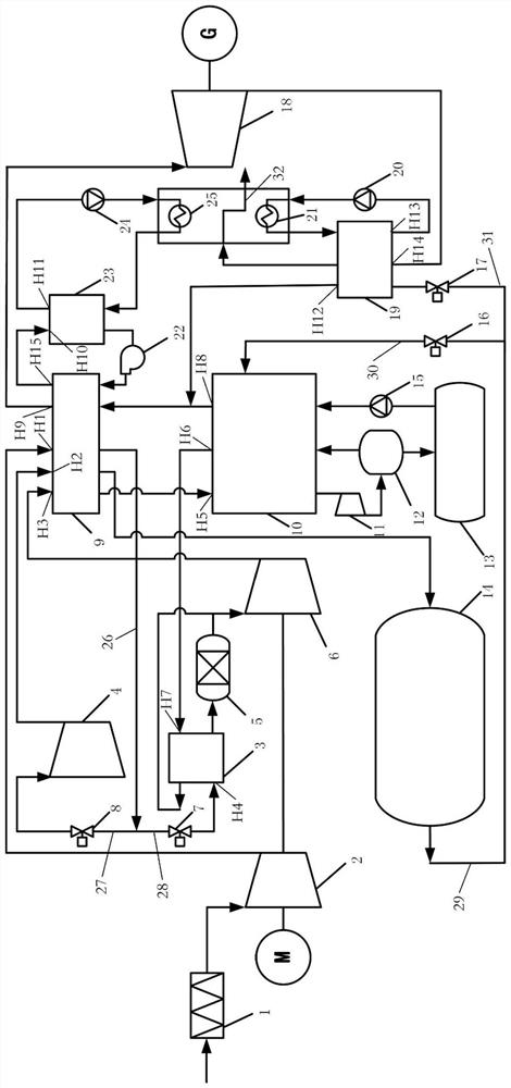
The invention provides a compressed air and liquid air combined energy storage power generation system. An outlet of a primary air compressor unit is connected with a compressed heat storage and utilization device. The compressed heat storage and utilization device is connected with a compressed air storage unit. The compressed heat storage and utilization device is connected with a liquid air storage unit. The compressed air storage unit and the liquid air storage unit are both connected with an expansion power generation unit. Through the structural arrangement, compressed air and liquid air combined power generation can be achieved. On one hand, the problem that the energy storage density of a compressed air energy storage power station is low can be solved; and on the other hand, the response rate of a liquid air energy storage power station can be increased. Thus, the flexibility and operation efficiency of an air energy storage system are effectively improved. Meanwhile, the compressed air energy storage power station and the liquid air energy storage power station share the primary air compressor unit, the compressed heat storage and utilization device and the expansion power generation unit, and the investment cost of facility equipment is greatly reduced.

Description

technical field [0001] The invention relates to the technical field of liquid air energy storage, in particular to a combined energy storage and power generation system of compressed air and liquid air. Background technique [0002] Air energy storage is an emerging large-scale green energy storage technology. Air energy storage includes compressed air energy storage and liquid air energy storage. Among them, the conventional compressed air energy storage power station has low energy storage density and large area, but the system is simple and the response is fast. The liquid air energy storage power station has high energy storage density and small footprint, but the system is complex and the response is slow. At the same time, when the compressed air energy storage power station and the liquid air energy storage power station are independently established, the corresponding equipment and facilities need to be set up respectively, and the investment cost is relatively lar...

Claims


Application Information

Patent Timeline
Patent Type & Authority Applications(China)
IPC IPC(8): F01K25/10F01K3/00F01K3/02F01D15/10
CPCF01K25/10F01K3/02F01K3/006F01D15/10
Inventor 季伟郭璐娜陈六彪崔晨郭嘉王俊杰
Owner 中绿中科储能技术有限公司
Learn More