Bymixer Apparatus and Method for Fast-Response, Adjustable Measurement of Mixed Gas Fractions in Ventilation Circuits

a bymixer and mixing gas technology, applied in the field of biomedical devices and methods, can solve the problems of limited use of such information, difficult cleaning and construction of prior art bymixers, and high cost, and achieve the effects of convenient further use of indirect calorimetry, convenient cleaning and construction, and convenient adjustment of respons

Inactive Publication Date: 2011-04-07
RGT UNIV OF CALIFORNIA
View PDF38 Cites 20 Cited by
  • Summary
  • Abstract
  • Description
  • Claims
  • Application Information

AI Technical Summary

Benefits of technology

[0011]The present invention provides a new bymixer device and method for obtaining fast-response, accurate measurements of mixed expired gas fractions in various types of ventilation circuits, including open (non-rebreathing) circuits, closed (rebreathing) circuits, circle (rebreathing with optional added fresh gas) circuits, etc. The bymixer is of a novel parallel design, which facilitates adjustable response, easy cleaning, and construction from standard airway circuit components. This bymixer may serve as a platform or enabling technology to facilitate further use of indirect calorimetry during anesthesia and / or mechanical ventilation in critical care settings.
[0013]Further in accordance with the present invention, all or a portion of the bymixer device (e.g., the mixing chamber) may be automatically or manually adjustable or variable in size such that the volume of respiratory gas contained in the mixing chamber may be varied. In combination with, or separately from, such adjustability in the size of the mixing chamber, the degree of flow restriction caused by the flow restrictor may also be automatically or manually variable. The adjustability in mixing chamber size and / or degree of flow restriction allows the bymixer device to be adjusted or adapted in a manner that optimizes the rate of response in measurements made on mixed gas samples from the mixing chamber versus the homogeneity of the mixed gas samples obtained from the mixing chamber. Also, such adjustability of mixing chamber volume and / or flow rate through the mixing chamber allows the operator to adjust the bymixer to accommodate patients of varying size and / or to maintain optimal mixing of respiratory gas and monitoring of variables even when changes occur in the ventilation circuit or in a given patient's ventilation parameters and / or clinical status.
[0014]Still further in accordance with the present invention, one or more flow-disrupting surfaces and / or one or more mixing apparatus (e.g., mixing vanes, a rotating impeller, vibrating surface, moving member, etc.) may optionally be positioned in the mixing chamber to further enhance the mixing of respiratory gasses within the mixing chamber.

Problems solved by technology

While these direct capnographic measurements at the airway opening do provide the clinician with important diagnostic information, the usefulness of such information is limited due to the fact that direct capnographic measurements of this type merely measure the partial pressure of CO2 without relating such measurement to the volume of respiratory gas that is passing through the airway opening as the measurement is taken.
This collection technique is time consuming and of limited value because the collected mixture of respiratory gas is obtained from only one location in the ventilation circuit (e.g., from the expiratory flow conduit).
However, such prior art bymixers were typically difficult to construct and thus somewhat expensive.
Also, the gas collection reservoirs of such prior art bymixers were of constant volume and the gas diverting tubes were of constant dimensions and, thus, could not be rapidly adapted or adjusted to accommodate patients of varying size (e.g., small pediatric patients and large adult patients) or changes that may occur in a particular patient's ventilation parameters or clinical status.
Finally, the gas collection reservoirs of the prior art bymixers were prone to collect condensed water vapor and respiratory debris and were difficult to clean.

Method used


Image

  • Bymixer Apparatus and Method for Fast-Response, Adjustable Measurement of Mixed Gas Fractions in Ventilation Circuits
  • Bymixer Apparatus and Method for Fast-Response, Adjustable Measurement of Mixed Gas Fractions in Ventilation Circuits
  • Bymixer Apparatus and Method for Fast-Response, Adjustable Measurement of Mixed Gas Fractions in Ventilation Circuits

Examples


Embodiment Construction

[0045]The following detailed description, and the accompanying drawings to which it refers, are provided for the purpose of describing and illustrating certain examples or specific embodiments of the invention only and not for the purpose of exhaustively describing all possible embodiments and examples of the invention. Thus, this detailed description does not in any way limit the scope of the inventions claimed in this patent application or in any patent(s) issuing from this or any related application.

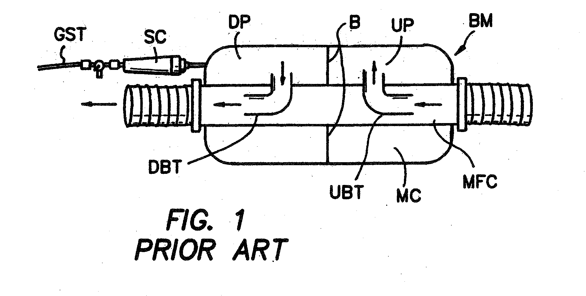
[0046]As shown in FIG. 1, a typical bymixer device of the prior art comprised a main flow conduit MFC that extends through a sealed mixing chamber MC. A right-angled upstream bypass tube UBT and a right-angled downstream bypass tube DBT extend through openings formed at longitudinally spaced-apart locations in the wall of the main flow conduit MFC, as shown. A porous baffle B divides the mixing chamber MC into an upstream portion UP and a downstream portion DP. A fraction of the respi...


PUM


Abstract

Bymixer devices and methods for sampling or obtaining data from mixed respiratory gases in a ventilation circuit. Respiratory gasses from a plurality of consecutive breaths become mixed within a mixing chamber of the bymixer and samples or data are obtained from such mixed respiratory gasses. Optionally, the volume of the mixing chamber and / or the resistance to flow into or through the mixing chamber may be selectable or adjustable.

Description

RELATED APPLICATIONS[0001]This is a continuation in part of U.S. patent application Ser. No. 10 / 530,602 filed Nov. 14, 2005, which is a 35 U.S.C. §371 national stage application of PCT / US03 / 33072 filed Oct. 14, 2003, which claims priority to U.S. Provisional Patent Application Ser. No. 60 / 417,982 entitled “Bymixer Apparatus for Fast-Response, Adjustable measurement of Mixed Expired Gas Fractions in the Anesthesia Circle Circuit and Related Method” filed on Oct. 11, 2002, the entire disclosure of each such application being expressly incorporated herein by reference.STATEMENT REGARDING FEDERALLY SPONSORED RESEARCH OR DEVELOPMENT[0002]This invention was made with government support under grant R01 HL-42637 awarded by the National Institute of Health. The government has certain rights in the invention.FIELD OF THE INVENTION[0003]The present invention relates generally to biomedical devices and methods, and more particularly to devices and methods for anesthesia, critical care medicine,...

Claims


Application Information

Patent Timeline
Patent Type & Authority Applications(United States)
IPC IPC(8): A61M16/10A61B5/08
CPCA61M16/12A61M16/208A61M16/22A61M16/161A61M2016/003A61M16/085A61M2230/432A61M16/0866
Inventor BREEN, PETER H.
Owner RGT UNIV OF CALIFORNIA
Why Eureka
Try Eureka