A small-flow miniature solenoid valve and its assembly and adjustment method

A solenoid valve, small flow technology, applied in the direction of valve device, valve details, valve operation/release device, etc., can solve the problems of low control precision and inconvenient adjustment method, achieve high measurement accuracy and avoid rubber modification problems , to avoid the effect of spool wear

Active Publication Date: 2022-03-04
HENAN AEROSPACE HYDRAULIC & PNEUMATIC TECH
View PDF20 Cites 0 Cited by
  • Summary
  • Abstract
  • Description
  • Claims
  • Application Information

AI Technical Summary

Problems solved by technology

[0005] In view of the deficiencies in the above-mentioned background technology, the present invention proposes a small-flow micro-solenoid valve and its assembly adjustment method and a small-flow micro-solenoid valve using the small-flow micro-solenoid valve and its assembly adjustment method, which solves the problem of the existing gas solenoid valve Low control accuracy, inconvenient adjustment methods and technical problems in service life

Method used


Image

  • A small-flow miniature solenoid valve and its assembly and adjustment method
  • A small-flow miniature solenoid valve and its assembly and adjustment method
  • A small-flow miniature solenoid valve and its assembly and adjustment method

Examples


Embodiment 1

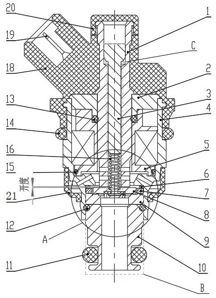
[0041] Embodiment 1, a kind of small flow miniature solenoid valve, such as figure 1 As shown, it includes a split valve body, and the valve body includes a split end housing 18, an intermediate housing 4, and an air outlet joint 10, and the end housing 18, the intermediate housing 4, and the air outlet joint 10 are detachably connected. .

[0042] A magnetizable sleeve 1 is arranged in the valve body, and a coil assembly 5 is arranged between the sleeve 1 and the valve body. The step platform 19 is axially fixed. The outer periphery of the armature 8 is provided with a magnetic isolation ring 7 , and the armature 8 can move axially under the magnetization of the coil assembly 5 . The lower end of the armature 8 is provided with a valve seat 9, and the top of the armature 8 is provided with a spring 16 that presses the armature 8 on the valve seat 9. When the coil assembly is not energized, under the elastic force of the spring 16, the armature 8 and the valve seat 9 Crimp ...

Embodiment 2

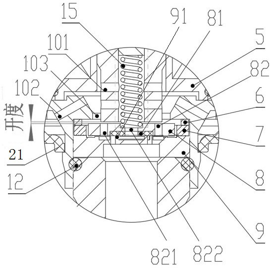
[0056] Embodiment 2, an assembly and adjustment method of a small-flow miniature solenoid valve, the end casing 18 is injected outside the sleeve 1, and the stopper 2 is installed outside the sleeve 1 before or after the injection molding of the end casing 18, and then The coil assembly 5 and the intermediate housing 4 are installed on the sleeve 1 and are clamped and fixed with the end housing 18. The second end of the intermediate housing 4 is installed with an adjusting pad 6, a magnetic isolation ring 7, an armature 8, and a valve seat 9. The intermediate housing 4 outside the seat 9 is connected with an air outlet joint 10 .

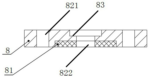
[0057] Further, the adjustment pin 3 and the spring 16 are inserted from the adjustment end or the other end of the sleeve 1, and the spring 16 is separately installed between the armature 8 and the adjustment pin 3 or is assembled with the installation groove 83 of the armature 8 and synchronized with the armature 8 Install.

[0058] Such as figu...


PUM


Abstract

The present invention discloses a small traffic micro -solenoid valve and its assembly adjustment method, including the split end housing, the middle shell, and the air outlet joint.Set up coil components. Set a two -armed, coil component, and iron gear on the sleeve. The peripheral of the armed iron is equipped with a magnetic ring. The top of the armed iron is set on the sprint of the armed iron on the valve seat, the coil component and the iron block are connected.Install the middle shell, the intermediate shell connecting the end of the terminal and the air outlet connector, the armed iron and valve seats are set between the middle shell and the air outlet joint.Inside the valve seat.The present invention can achieve accurate measurement control of the amount of gas jet, and respond to the needs of the CPU in a timely manner, so as to meet the best air -fuel ratio and meet the emission requirements.The elasticity of the itinerary and the toddler is opened.

Description

technical field [0001] The invention relates to the technical field of gas injection solenoid valves, in particular to a small-flow miniature solenoid valve and an assembly and adjustment method thereof. Background technique [0002] Solenoid valve is an industrial equipment controlled by electromagnetism. It is an automatic basic component used to control fluid and belongs to actuator. It is used to adjust the direction, flow, speed and other parameters of the medium in the industrial control system. Solenoid valves can cooperate with different circuits to achieve the expected control, and the control accuracy and flexibility can be guaranteed. At present, most of the gas metering solenoid valves used in engines in China have problems such as inaccurate gas metering control, unstable flow, and leakage, so that the best air-fuel ratio cannot be achieved, and the emission requirements cannot be met; and the existing gas metering solenoid valves When the electromagnet is in ...

Claims


Application Information

Patent Timeline
Patent Type & Authority Patents(China)
IPC IPC(8): F02M21/02F02D19/02F02D41/00F16K31/06
CPCF02M21/0248F02M21/0254F02M21/0257F02D19/024F02D41/0027F16K31/06F16K31/0675Y02T10/30
Inventor 胡丽敏侯涛杨亚青刘宝林冯楠刘刚李远葛赛张万年
Owner HENAN AEROSPACE HYDRAULIC & PNEUMATIC TECH
Why Eureka
Try Eureka