Small-flow miniature electromagnetic valve and assembling and adjusting method thereof
An adjustment method and electromagnetic valve technology, applied in the direction of valve details, valve devices, valve operation/release devices, etc., can solve the problems of inconvenient adjustment methods and low control accuracy, and achieve the avoidance of rubber modification problems and high measurement accuracy , Significant effect on environmental protection
- Summary
- Abstract
- Description
- Claims
- Application Information
AI Technical Summary
Problems solved by technology
Method used
Image
Examples
Embodiment 1
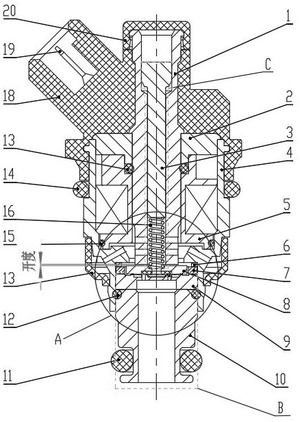
[0041] Embodiment 1, a kind of small flow miniature solenoid valve, such as figure 1 As shown, it includes a split valve body, and the valve body includes a split end housing 18, an intermediate housing 4, and an air outlet joint 10, and the end housing 18, the intermediate housing 4, and the air outlet joint 10 are detachably connected. .
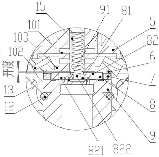
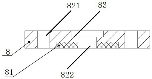
[0042] A magnetizable sleeve 1 is arranged in the valve body, and a coil assembly 5 is arranged between the sleeve 1 and the valve body. The step platform 19 is axially fixed. The outer periphery of the armature 8 is provided with a magnetic isolation ring 7 , and the armature 8 can move axially under the magnetization of the coil assembly 5 . The lower end of the armature 8 is provided with a valve seat 9, and the top of the armature 8 is provided with a spring 16 that presses the armature 8 on the valve seat 9. When the coil assembly is not energized, under the elastic force of the spring 16, the armature 8 and the valve seat 9 Crimp ...
Embodiment 2
[0056] Embodiment 2, an assembly and adjustment method of a small-flow miniature solenoid valve, the end casing 18 is injected outside the sleeve 1, and the stopper 2 is installed outside the sleeve 1 before or after the injection of the end casing 18, Then install the coil assembly 5 and the middle housing 4 on the sleeve 1 and clamp and fix them with the end housing 18. The second end of the middle housing 4 is installed with an adjustment pad 6, a magnetic isolation ring 7, an armature 8, and a valve seat 9. , the intermediate housing 4 outside the valve seat 9 is connected to the gas outlet joint 10 .
[0057] Further, the adjustment pin 3 and the spring 16 are inserted from the adjustment end of the sleeve 1 or the other end or the other end, and the spring 16 is separately installed between the armature 8 and the adjustment pin 3 or assembled with the installation groove 83 of the armature 8 Followed by armature 8 synchronous installation.
[0058] Such as figure 1 B i...
PUM
 Abstract
Description
Claims
Application Information
 - R&D
- Intellectual Property
- Life Sciences
- Materials
- Tech Scout
- Unparalleled Data Quality
- Higher Quality Content
- 60% Fewer Hallucinations
Browse by: Latest US Patents, China's latest patents, Technical Efficacy Thesaurus, Application Domain, Technology Topic, Popular Technical Reports.
© 2025 PatSnap. All rights reserved.Legal|Privacy policy|Modern Slavery Act Transparency Statement|Sitemap|About US| Contact US: help@patsnap.com


